Dynalyzer – High Voltage Unit
OPERATION MANUAL
8
Installation
Inspection
Inspect the unit after receipt for signs of physical damage. Report any damage to the carrier at
once if any occurred in shipping.
Observe that tank pressure is within the 15-30 psi range. If the pressure is below 10 psi, the unit
should be recharged. Refer to the Maintenance section.
Verification of the operation of the unit may be made with the aid of a digital voltmeter (DVM). Plug
the line cord into the 115 VAC, 60 Hz power source. Measure the output voltages from the BNC
output connectors. All voltages should be within ± 1 millivolt with respect to ground. Operation may
be verified by actual operation or by preliminary low-voltage calibration techniques.
Reasonable care should be taken in the handling of this unit as undue shock may loosen the
integrated circuits from their sockets or upset the optical system in the current detection unit.
The equipment setup depends on the tests to be performed and the auxiliary equipment used.
Details are contained in subsequent paragraphs.
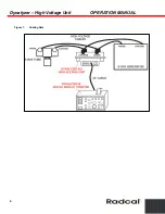
This section describes the proper techniques for the installation of the High Voltage Unit for
calibrating or diagnostic investigation of an x-ray installation. The user is again cautioned about
possible safety hazards due to the presence of high voltage x-ray radiation, and is requested to
review the safety notice in the Preface.
Parts Necessary for Use
Two 12-foot long RG-58U cables with BNC connectors at each end for oscilloscope connections.
(Supplied)
Besides the High Voltage Unit, the following parts are required:
•
Two high-voltage cables, approximately 5 feet long with ASA (Federal) terminals at each
end
•
Two ASA (Federal) dummy high-voltage receptacle plugs (Supplied)
•
Two 1.5 oz. tubes of vaporproofing compound for cables and plugs (Supplied)
•
Small quantity of alcohol for cleaning high-voltage cable receptacles and terminals
•
A piece of lead sheet 0.5 in. thick for blocking x-ray tube port, if no collimator is present
•
A digital voltmeter
A differential input scope is not necessary as a composite A + C output is provided. Dual-trace or
dual-beam capability is desirable to allow mA and kV to be viewed simultaneously.
NOTE:
If the oscilloscope does not have a storage feature, an oscilloscope camera will be
useful to permit analysis of the waveform after the trace fades.
•
A BNC for binding post adapter (if needed)


