Dynalyzer – High Voltage Unit
OPERATION MANUAL
10
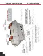
1. Use the shortest high-voltage cable jumper as physically possible between the High
Voltage Unit and the x-ray tube (recommended length 5 feet).
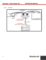
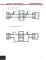
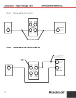
2. Insert both the anode and cathode sections of the High Voltage Unit in the x-ray circuit.
(See Figure 3).
3. For each desired measurement, record the anode kVp required to obtain the anode to
cathode kVp at the mA of interest.
4. Remove the cathode side of the High Voltage Unit from the circuit, leaving the anode side
connected, and complete the circuit from the high tension transformer to the x-ray tube.
(See Figure 4).
5. Readjust the kVp and mA to precise values using the anode kVp readings and mA
readings. This eliminates the effect of the added cathode cable insertion.
The setup as shown in Figure 4 may also be employed in grid-pulsed applications to accurately
determine anode kVp and x-ray tube current. This technique does not measure cathode kVp or
filament current because the cathode side of the Dynalyzer is not connected.
Series Parallel Connection
This method can only be used with x-ray generators having auxiliary high-voltage
receptacles capable of simultaneous activation.
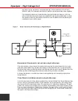
This setup shown in Figure 7 enables the measurement of all parameters except filament
current and eliminates the possible adverse effect of an additional test cable in the filament
circuit.
NOTE:
The Dynalyzer III has been designed for remote reading to minimize x-ray danger to
the operator.
CAUTION:
The High Voltage Unit, Digital Display and oscilloscope must be connected to
the same grounded outlet or damage may result to the equipment and/or the
accuracy of the readings may be affected.


