Dynalyzer – High Voltage Unit
OPERATION MANUAL
16
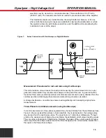
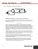
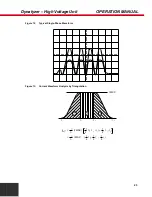
Figure 8:
Typical Three-Phase Current Waveform
Fluoroscopic Current Measurements (using Oscilloscope)
For these measurements, the front panel switch should be set to the FLUORO position. Three-
phase fluoroscopic current measurements can be evaluated per the Three-Phase Current
Measurements section above. Single-phase fluoroscopic measurements may fall into two
categories: 1) filtered and 2) unfiltered. At low current levels (below 5 mA) in systems with
sufficient cable, or external capacitor banks, the voltage applied to the x-ray tube may appear to be
purely direct current. The current waveform will depend on the location of the Dynalyzer High
Voltage Unit with respect to the x-ray tube. Use the FLUORO position if there is significant low
level noise filtering by the amplifier circuitry in the High Voltage Unit.
Measurements with Digital Display
The Dynalyzer II or III Digital Display can be used in conjunction with the high voltage unit to
provide the following five measurements simultaneously:
1. mA and mAs
2. Exposure time (triggered by kV, mA, external trigger or internal (line) trigger
3. kVp of anode or cathode only or both
4. Auxiliary readout of filament current or line voltage
An oscilloscope can be connected in conjunction with the Digital Display to obtain a visual image of
the waveform measured. Refer to the Digital Display Instructions for additional information.
Current Measurements with Dynalyzer III Digital Display (mA and mAs)
The Dynalyzer III Digital Display contains all necessary signal processing required for accurate
measurements of either mA or mAs in all modes described above. In operation, the incoming

