Dynalyzer – High Voltage Unit
OPERATION MANUAL
17
analog signal is digitized, and the resulting pulses are stored. Thus, the pulse count gives a true
indication of the mAs of an exposure. Simultaneously with the current integration, the exposure
time is being counted by a digital clock. The average current is displayed by electronically dividing
the mAs by time.
Triggering for this measurement may be made with current, voltage, external trigger, or manually
(auto mode).
Exposure Duration (Time)
The third line of the display is the exposure time that is triggered by the kV, mA, auto (internal), or
an external signal.
Dynalyzer Digital Display of kVp Measurements
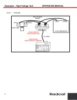
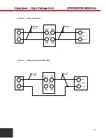
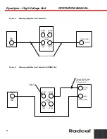
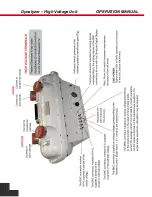
The Dynalyzer Digital Display is interconnected to the High Voltage Unit with a 20-foot long
shielded cable. The Digital Display is powered from the 120/240 VAC, 50/60 Hz line.
kVp measurements are made by selecting either the sum of Anode + Cathode or the individual
terminals with respect to ground. The Digital Display is triggered by dialing in the fraction of the
peak or preset (absolute) amount of kVp or mA that is considered the beginning of the exposure,
i.e., 0-10% for single-phase and 75% for three-phase operation. A test exposure is made to set the
gain factor of the display. Each subsequent exposure will trigger both the peak detector circuit and
the electronic time clock. Both kVp and time in milliseconds will be displayed. (Current and filament
will also be displayed.) A delay, adjustable up to 20 milliseconds, is provided to prevent
measurement of the leading edge which may contain substantial overshoot of a three-phase
exposure.
In both single and three-phase exposures, the kVp displayed will be the highest value within the
exposure, with the exception of the kVp present during the delayed period.
Details on operation are supplied in the Digital Display Instruction Manual supplied with the Display
Unit.
Filament Current Measurement with the Dynalyzer Digital Display
Pressing MANUAL TRIGGER after selecting AUTO at the TRIGGER SOURCE switch on the
display causes the filament current to be displayed at an update rate of 0.5 second.
Measurements with Suitable RMS Voltmeter
An ac rms voltmeter, such as the Data Technology Model 31 may be used to obtain a readout of
the filament current.
Rms conversion modules are available from Analog Devices, Burr-Brown, and Intronics, as well as
other manufacturers. These modules require ± 15 VDC power to operate and a digital voltmeter to
display their output.

