Dynalyzer – High Voltage Unit
OPERATION MANUAL
3
Introduction
General
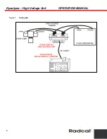
The Dynalyzer III High Voltage Unit is capable of providing isolated signals analogous to:
1. Anode, Cathode, and Anode + Cathode kilovoltages
2. Anode
Current
3. Filament Current (AC)
These signals may be viewed on an oscilloscope, may be measured with a voltmeter, or may be
processed and displayed with the Dynalyzer Digital Display.
This unit has been designed as a calibration instrument and as a diagnostic tool for servicing x-ray
equipment.
This unit is designed for continuous duty, and may be left in the high-voltage circuit indefinitely, if
desired. This feature is desirable in special applications where frequent calibration is required.
This unit is portable. It weighs 32 pounds and is designed to simplify servicing and repair.
Basic Principle of Operation
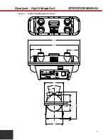
The Dynalyzer High Voltage Unit is built in two sections. All high-voltage components are located
in a tank pressurized with 30 psig of Sulfur Hexafluoride (SF
6
) gas. In the base of the unit are
power supplies and buffer amplifiers to adjust the levels of the isolated signals, provide buffering
against cable and instrument loading effects, and provide frequency compensation. In addition,
there is an oscillator which in conjunction with a high-frequency isolation transformer located in the
tank, provides power to operate the anode current sensing system.
Anode Current Sensor
The anode current sensor is an optically-coupled device that is capable of providing an isolated
signal that represents the anode current waveform. The sensor is capable of measuring current in
the range of 1 mA to 2 Amperes with a 2% absolute accuracy ± zero offset. The output conversion
factor is 1 mV/mA for fluoroscopic measurements. The insertion impedance of the unit is 200 ohms
± 5%. The average power rating of this resistor network is 10 watts, and is the only duty cycle
limitation on this unit. The kVp rating is 150.
High-Voltage Divider
The divider consists of two 1000 megaohm sections that are connected between the anode and
ground, and cathode and ground. Each section contains ten (10) 100 megaohm resistors
connected in series. The geometry of the structure provides distributed capacitance that allows a
frequency response of 100 kHz to be obtained by adjustment of the buffer amplifier compensation
capacitor.
Filament Current
Filament current is measured in the common lead of the cathode circuit using an insulated AC
toroidal transformer. The output of the transformer, which is loaded with a 1 ohm resistor, is


