background image

40

EN

16.  Automatic solar function

The automatic solar function enables brightness-dependent 
control of the roller shutters in combination with the light sensor. 
To do this, the light sensor is secured to the window pane with a 
suction cup and then plugged into the Troll Basic 5602.

Automatic solar function

Automatic moving up and down of the roller shutter once a set 
limit is exceeded. The roller shutter end position can be freely 
selected by changing the light sensor position.

Automatic lowering

If the sensor detects uninterrupted sunlight for 10 minutes, 
the shutter will descend until its shadow covers the  
light sensor.

10 mins 

sun

Summary of Contents for 3650 01 12

Page 1: ...VBD 599 2 01 21 Item no 3650 01 12 ultra white EN Troll Basic 5602 Instruction manual for the electrical connection and for commissioning Type 5602 ...

Page 2: ...Unit 11 5 1 General View of the Installation Housing 13 5 2 Electrical connections 14 5 3 Function of the buttons and LEDs 15 6 Product Description 16 6 1 Compatible switches 17 6 2 Overview of Features 18 7 Technical Specifications 19 7 1 Factory Settings 22 7 2 Conduct in the event of power failure 22 8 Important information prior to electrical installation and mounting 23 9 Safety Instructions ...

Page 3: ...ctions on off simultaneously Auto Manu switchover 36 15 Automatic timer 37 15 1 Configuring an opening and closing time 38 15 2 Switching the automatic timer on off 39 16 Automatic solar function 40 16 1 Automatic solar function configuring sensitivity 42 17 Automatic dusk function 44 17 1 Automatic dusk function configuration of sensitivity 46 18 Dimming the LEDs 48 19 Hardware Reset in the event...

Page 4: ... manuals of the accessories if available as well as the instructions of the respective connected appliance This manual is a component of the product Please store it in an easily accessible place When passing the Troll Basic 5602 on to a third party this manual must be passed on as well Damage resulting from non compliance with these instructions and safety instructions will void the guarantee We a...

Page 5: ...angerous situation 2 1 Levels of danger and signal words DANGER This hazard will lead to serious injury or death if not avoided WARNING WARNING This hazard may result in serious injury or death if not avoided CAUTION This hazard may result in minor or moderate injury if not avoided ATTENTION This hazard may lead to property damage i ...

Page 6: ...depictions used Depiction Description 1 Procedures 2 Itemisation 1 or a Lists i further useful information Please read the respective manual Indicator light flashes red Indicator light lights up red Indicator light is off i ...

Page 7: ... use leads to an increased risk of injury Train all personnel to use the Troll Basic safely This device may be used by children from 8 years of age upwards as well as by persons with reduced physical sensory or mental capacities or with lack of experience and knowledge if they are supervised or have been instructed on how to use the device safely and if they understand what dangers may resulted fr...

Page 8: ...st be fitted with a mechanical or electronic end position switch 3 2 Incorrect Use Using the Troll Basic 5602 for any other purpose than previously mentioned is not permissible Improper use can lead to serious injuries or property damage TheTrollBasic5602isnotsuitabletobeusedforanelectrically safe disconnection of the connected appliances There is a risk to life caused through short circuiting and...

Page 9: ...commissioning of the Troll Basic 5602 must only be carried out by a qualified electrician in accordance with the instructions in this manual 3 4 Glossary Definition UW UW ultra white device colour DIN 49075 German Standard Cover panels for installations devices for building into device boxes i i ...

Page 10: ...x 50 mm b 1 x Frame c 1 x Installation housing d 1 x Spacer frame see page 32 e 1 x Instruction manual not illustrated After unpacking please check and compare the contents of the package with the above specified Accessories optionally available see page 52 Light sensor a b c d ...

Page 11: ...bol Description 1 Operating unit 2 Sun LED red 3 Timer LED red 4 Dusk LED red 5 Timer button Switch the automatic timer on off 6 Sun button Switch the automatic solar function on off 7 Dusk button Switch the automatic dusk function on off 4 5 6 7 8 9 10 11 12 ...

Page 12: ...the current drive see page 35 10 SET key Configuration setting of various functions The functions are respectively set in combination with the other buttons see table on page 15 11 AUTO MANU key Switch all automatic functions on off simultaneously 12 Connection socket for the light sensor Installation see page 30 5 GeneralView of the Operating Unit i ...

Page 13: ...eneralView of the Installation Housing 13 15 Pos Symbol Description 13 Installation housing 14 Plug in coupling for the operating unit 15 Claw fasteners and screws 16 Connecting terminals 17 Type plate i 17 16 14 ...

Page 14: ...rallel connection of several devices is possible on both inputs E1 E2 and the Troll Basic 5602 must be connected to the same phase L see page 25 19 E2 E1 L N Voltage supply L N 230V 50 Hz Connection of the supply voltage 20 E2 E1 L N Rotational direction Down Up Connecting cables to the tubular motor 5 2 Electrical connections 19 i 20 ...

Page 15: ...off 1 sec Switch automatic mode on off 1 sec Settings Button combinations Accept the current time as the opening time 1 sec Accept the current time as the closing time 1 sec Adopting the current brightness as the set limit 1 sec Adopt the current brightness dusk as the set limit 1 sec Set the running time 4 sec Software reset 4 sec 5 3 Function of the buttons and LEDs ...

Page 16: ...oll Basic 5602 features two inputs E1 and E2 230 V 50 Hz for connecting an external push button or external controller see page 28 Installation and electrical connection The Troll Basic 5602 is designed as a flush mounted device for indoor rooms The electrical connection is carried out by means of the connecting terminals on the reverse side of the installation housing The Troll Basic 5602 can be ...

Page 17: ...clusive alpha nea solo impuls GIRA Standard System S Color System Stainless steel Standard 55 JUNG CD 500 ST 550 LS 990 CDplus and CD however with coloured rings MERTEN M1 Atelier Artec Trancent Antique New PEHA Standard Dialog Aura LEGRAND Creo Tenara VEDDER Alessa plus i It may be necessary to use an intermediate frame 50 x 50 according to DIN 49075 depending on the respective switch range used ...

Page 18: ...ensor on off Switch automatic dusk function with light sensor on off External control via the two inputs E1 E2 Setting options Adoption of the current time as the switching time Adoption of the current brightness as a new brightness set limit for the automatic solar function Adoption of the current brightness dusk as a new brightness set limit for the automatic darkness function Dimming the LEDs D...

Page 19: ...ical Specifications Connection of the tubular motor s and t Switching voltage 230 V 50 Hz Maximum switching capacity ohmic load e g bulb 8 A µ type 1B inductive loads such as fluorescent lamps drives iron core transformers e g for extra low voltage bulbs such as halogen bulbs 4 A µ type 1B M ...

Page 20: ...c 4 A µ type 1B Inputs E1 s E2 t For an external manual push button or an additional exter nal control see page 25 28 Input voltage 230 V 50 Hz Improper use can lead to serious injuries or property damage Due to the small contact distance µ not suitable for disconnecting TheTrollBasic5602isnotsuitabletobeusedforanelectrically safe disconnection of the connected tubular motor 7 Technical Specificat...

Page 21: ...missible ambient temperature range 0 C to 40 C Protection class II only for use in dry rooms Protection type IP 30 Connecting terminals Screw terminals for max 1 5 mm2 cables cross section Setting ranges Sensitivity to sunlight 4 000 to 40 000 Lux Dusk sensitivity 2 to 50 Lux The current brightness can respectively be adopted as a set limit 7 Technical Specifications i ...

Page 22: ...e timer stands still Data retention following a power failure All settings also the configured switching times are retained after a power failure As soon as the power supply is restored the opening and closing times will be executed again however the times will be delayed by the duration of the power failure If required set the switching times again if you do not wish to keep the delayed switching...

Page 23: ...he operating manual for the corresponding tubular motor Parallel connection of electronic tubular motors A maximum of 3 tubular motors can be connected in parallel to theTrollBasic5602 e g RADEMACHERelectronictubularmotors Parallel connection of mechanical tubular motors A cut off relay is required in order to connect mechanical tubular motors in parallel Installation materials The Troll Basic 560...

Page 24: ...602 is overloaded poses a danger to life The maximum switching capacity must not be exceeded for this please observe the details in the Technical Specifications see page 19 DANGER There is a risk of fatal electric shocks when touching electrical components All connection and installation work must only be carried out in a de energised state Disconnect all phases of the mains power supply cable and...

Page 25: ...R products are not compatible WARNING WARNING Incorrect wiring may lead to short circuits and destroy the device Follow the pin assignment detailed in the wiring diagram Connection of a second phase to E1 or E2 will cause the Troll Basic 5602 to be damaged When the inputs E1 E2 are used the external push button controller and the Troll Basic 5602 must be connected to the same phase L If another ph...

Page 26: ...tion of external push buttons The maximum length of lead to connect an external switch push button must not exceed 10 m Length of insulation stripped 6 mm All leads must be stripped to 6 mm 9 Safety Instructions for the Electrical Connection i ...

Page 27: ...nnect them according to the following connection diagram 4 After the electrical connection the installation of the Troll Basic 5602 into the flush mounted box is carried out see page 29 9 1 Connecting a tubular motor Connecting the white set cord SET from RADEMACHER tubular motors The white set cord SET from RADEMACHER tubular motors must be connected to the neutral terminal N to ensure trouble fr...

Page 28: ...28 EN 9 2 Connection Diagram withTubular Motor Tubular motor i Inputs E1 E2 230 V 50 Hz only if required ...

Page 29: ...nstallation housing into the flush mounted box and fasten it with the screws of the claw fasteners 2 Place the frame onto the installation housing 3 Subsequently carefully insert the operating unit into the installation housing 4 Switch on the mains power supply again i ...

Page 30: ...ct the optionally available RADEMACHER light sensor to the Troll Basic 5602 11 Connecting a light sensor i 11 1 Light sensor connection when using the supplied frame i 1 Carefully pull the operating unit off the installation housing 2 Insert the light sensor plug into the socket on the rear of the operating unit Accessories see page 52 ...

Page 31: ...fully replace the operating unit with frame back onto the installation housing ATTENTION Excessive bending can damage the sensor cable The sensor cable is a fibre optic cable Avoid excessive bending or crushing of the sensor cable 11 1 Light sensor connection when using the supplied frame i ...

Page 32: ...itionally provided spacer frame onto the rear of the operating unit It may be necessary to use an intermediate frame 50 x 50 DIN 49075 depending on the respective switch range used not included 11 2 Light sensor connection when using a frame supplied by a third party manufacturer i Intermediate frame Spacer frame ...

Page 33: ...ation housing 2 If the sensor cable has been fixed in place by means of the operating unit s engagement hooks then it must first be released for example with the help of a 50 cent coin 3 Pull the light sensor plug out of the socket 4 Replace the operating unit back onto the installation housing ...

Page 34: ... initial commissioning of the Troll Basic 5602 it must be ensured that the end points are configured for the connected tubular motor If no end points are configured then it is vital that both end points are configured for the tubular motor as failure to do so can lead to malfunctions Please refer to the operating manual for the corresponding tubular motor ...

Page 35: ...e inputs E1 E2 t t i Manual operation is always possible and has priority over the automatic functions 1 Open the roller shutters Briefly pressing the button causes the roller shutters to move to the upper end point 2 or Stop the shutters in the interim 3 Close the roller shutters The roller shutters move to the lower end point Example for manual control of a roller shutter ...

Page 36: ...D The automatic timer can only be switched on if a switching time has been previously set 14 1 Switch all automatic functions on off simultaneously Auto Manu switchover 1 1 sec Press and hold the AUTO MANU button for approx 1 second 2 All previously activated automatic functions will be simultaneously switched on or off 3 Observe the respective LEDs indicating the status of the automatic functions...

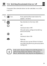
Page 37: ...ttings at any time Please note that each new switching time deletes the previous setting i In order to set the switching times you must carry out this step once at the time that the roller shutters are to open or close For example carry out the step at 8 00 o clock in the morning if you want the roller shutters to open at 8 00 AM every day You must set at least one switching time in order to activ...

Page 38: ...hutter travels upwards The automatic timer is now activated Your roller shutters will open automatically every day at 8 00 AM Configure a closing time e g at 20 30 hours 1 1 sec Simultaneously briefly press the buttons 2 ThetimerLEDflashesandtherollershutter travels downwards The automatic timer is now activated Your roller shutters will close automatically every day at 20 30 ...

Page 39: ...2 Pay attention to the timer LED OFF Automatic timer OFF The previously configured switching times are stored ON Automatic timer ON Flashing After previous power failure if at least one switching time has previously been configured i In the event of power failure the switching times will be extended by the duration of the power failure and therefore may require reconfiguration ...

Page 40: ...e with a suction cup and then plugged into the Troll Basic 5602 Automatic solar function Automatic moving up and down of the roller shutter once a set limit is exceeded The roller shutter end position can be freely selected by changing the light sensor position Automatic lowering If the sensor detects uninterrupted sunlight for 10 minutes the shutter will descend until its shadow covers the light ...

Page 41: ...ess decreases below the set limit it returns to the upper end point i The above mentioned delay times can be exceeded in the event of changing weather conditions The automatic solar function will be terminated and must be reactivated if required after the following events After manual actuation After execution of an automatic function After the upper end point is reached After 20 mins 16 Automatic...

Page 42: ...utomatic solar function 1 1 sec Simultaneously briefly press the buttons 2 The current brightness is now set as the set limit and the automatic solar function is activated If this value is exceeded the roller shutters will roll down to the light sensor 3 Observe the solar LED OFF Automatic solar function OFF ON Automatic solar function ON Flashing u if the set limit is exceeded u if the current br...

Page 43: ... the measuring range the set limit is set to the measured range limit 4 You can switch the automatic solar function on and off as required 5 1 sec In order to do so press and hold the sun key for approx 1 second 16 1 Automatic solar function configuring sensitivity ...

Page 44: ...en dusk is detected for a minimum of 15 seconds The light sensor has been mounted and plugged into the Troll Basic 5602 Automatic lowering At dusk the roller shutters will lower to the lower end point after approx 15 seconds The roller shutters will open again once the configured opening time is reached or in the event of a manual UP command The required darkness limit is configurable ...

Page 45: ...losing time to a time after dusk see example If an automatic closing command is given before dusk triggers then the automatic dusk function will not be executed 17 Automatic dusk function Example 1 2 Automatic closing time 23 00 19 30 Onset of dusk 20 30 20 30 The roller shutters auto matically close at 20 30 19 30 ...

Page 46: ... current brightness is now set as the set limit and the automatic dusk function is activated If this value is exceeded the roller shutters will roll down to the lower end point 3 Observe the dusk LED OFF Automatic dusk function OFF ON Automatic dusk function ON Flashing u if the set limit is exceeded u if the current brightness value is within the measured range while configuring the set limit Set...

Page 47: ...apid flashing If the current brightness value is outside the measuring range the set limit is set to the measured range limit 4 You can switch the automatic dusk function on and off as required 5 1 sec In order to do so press and hold the dusk key for approx 1 second ...

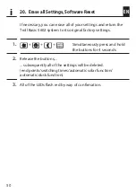
Page 48: ... will be switched on for at least 10 seconds Set the overall running time of the roller shutter 1 First fully close the roller shutters 2 Then first press and hold the SET button and then also the UP button together 3 After approx 4 seconds the timer LED will flash to confirm and the roller shutters move to the upper end point 4 Release both buttons immediately as soon as the roller shutter reache...

Page 49: ...en there is power failure 1 Carefully pull the operating unit off the installation housing 2 Wait approx 5 seconds and then carefully reinsert the operating unit into the installation housing 3 Subsequently check that the Troll Basic 5602 is functioning correctly 4 If the Troll Basic 5602 is still not reacting carry out a software reset see page 50 and test the Troll Basic 5602 with the factory se...

Page 50: ...roll Basic 5602 system to its original factory settings 1 Simultaneously press and hold the buttons for 4 seconds 2 Release the buttons subsequently all of the settings will be deleted end points switching times automatic solar function automatic dusk function 3 All of the LEDs flash red by way of confirmation ...

Page 51: ...d 1 Switch off the mains power secure it from restarting and check that the system is de energised 2 Carefully pull the operating unit off the installation housing 3 Remove the frame 4 Release the claw fasteners of the installation housing and pull it out of the flush mounted box 5 Disconnect the connecting cable from the installation housing 6 Securetheconnectionpointagainstrestartingandtheconnec...

Page 52: ...irecive and 2014 30 EU EMC directive The full text of the declarations of conformity is available at the following website www rademacher de ce 23 Accessories Further information about our accessories is available at the following website www rademacher de zubehoer Light sensor Item No Cable length 7000 00 88 0 75 m 7000 00 89 1 5 m 7000 00 90 3 m 7000 00 91 5 m 7000 00 92 10 m i ...

Page 53: ...epairs and modifications by third parties unauthorised persons Use of unsuitable accessories Damage caused by unacceptable excess voltage e g stroke of lightning Operational malfunctions caused by radio frequency overlapping and other such radio interference A prerequisite for the warrant is that the new device must have been purchased from one of our approved specialist retailers Proof of this mu...

Page 54: ...e Service Hotline 01807 933 171 Fax 49 2872 933 253 service rademacher de 30 seconds free of charge subsequently 14 cents minute from German fixed line networks and max 42 cents minute from German mobile networks Subject to technical modifications misprints and errors excepted Illustrations not binding ...

Reviews: