- Page 18 -
5.3.2
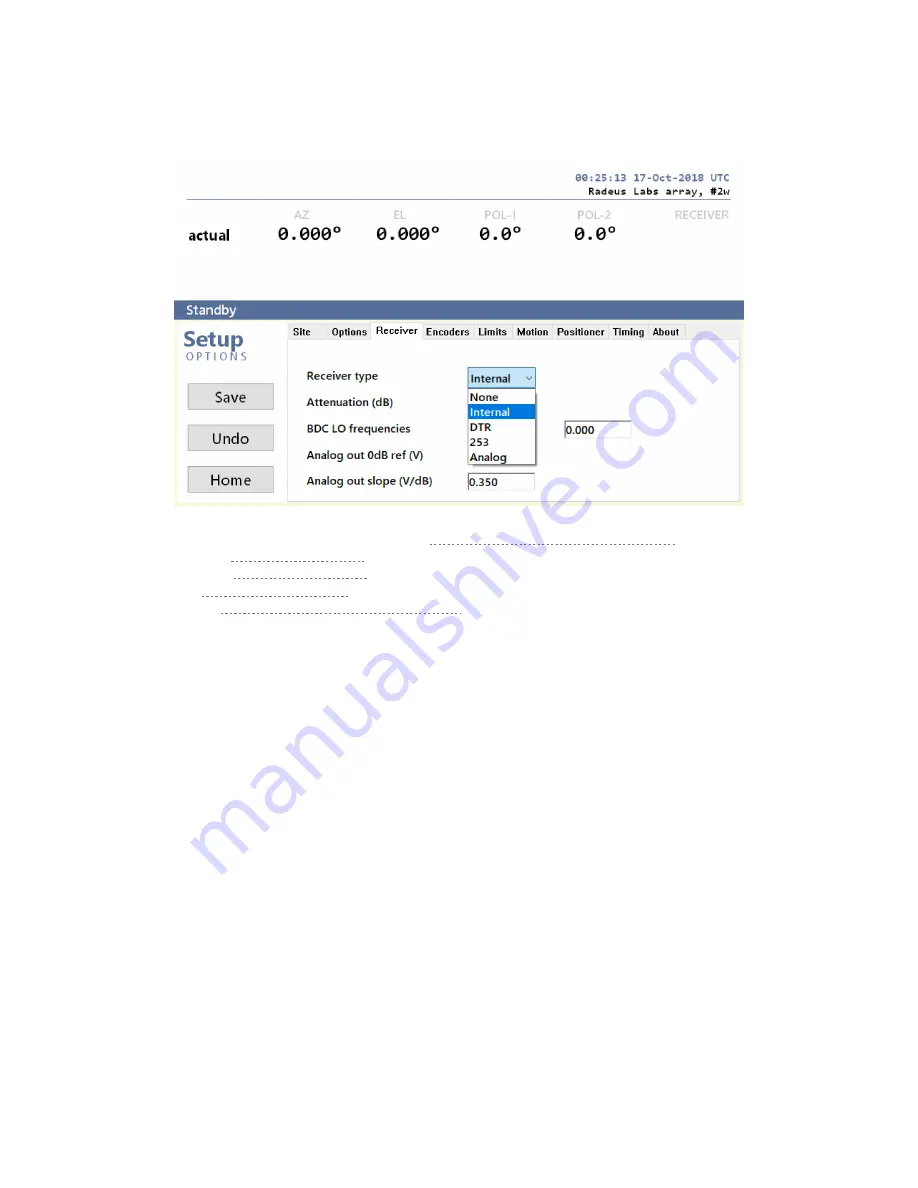
Enter the receiver’s characteristics
For details, refer to the relevant appendices in the
Series 8000 ACS Operation & Maintenance
Encoders: see
Resolvers: see
DTR: see
GD 253: see
“Setup: GD Model 253 Tracking Receiver”
1.
For the BDC LO frequency, enter the vertical and horizontal values (or left and right, for
circular polarization).
2.
The receiver attenuation, in dB.
3.
Specify the upper and lower limits of the frequency range, in any order.
The optional, built-in beacon receiver has a 0
–
10V analog output. In the next fields, specify:
4.
The reference voltage for the
relative
power level of 0dB. (A related offset is defined in
each target’s settings. For an example, select a target at Home > Target and choose Edit
to inspect its related setting.)
5.
The output’s slope (V/dBm).


