background image

“bottom-out” onto the breech block when the six male gold connectors fully seat inside the six female 
gold connectors located near the front/center of the breech block.  Connections for the 4 signal wires 
and two LED stylus spotlight wires are now complete. 

WARNING:  The bearings are stainless steel, the pivot points are 10.9 steel, but the inner gimbal is 
Delrin.  The bearings and pivots are rigid, but Delrin has some flexibility by nature.  If pushed without 
any constraining support it is possible to flex the Delrin enough so that a pair of bearing/pivots could 
be pressured to unseat (as opposed to break).  The method described here for wand insertion and 
extraction works well, and MUST be practiced without any exceptions. 

extraction works well, and MUST be practiced without any exceptions. 

Vertical Tracking Force

: For normal cartridges, now would be the time to utilize a vertical force gauge 

and adjust the counterweight position to comply with the cartridge manufacturer’s stylus force 
recommendations. 

Vertical cartridge alignment tool

The green vertical cartridge alignment tool comes pre-mounted on the lightweight ladder wand.  It is the 
last check that is made before shipment.  Since the green vertical alignment tool can be pressed down 
onto the platter surface manually by finger pressure, setting tracking force is not yet required 

This tool insures that the stylus will be standing up perfectly straight when attached to the cartridge 
mounting pad.  Less than perfect vertical could be the result of either the front tower’s elevator or the 
back tower’s elevator not being adjusted to exactly at the same vertical displacement from the tone 
arm’s base plate surface. 

arm’s base plate surface. 

Press the blue LED button to send the lift/lower motor into cycling the wand down toward the platter.  
Manually push the green cartridge alignment tool down onto the platter and observe whether any light 
is present at the left or right bottom edge.  If present, then adjust one of the tower elevators to 
compensate.  Read the next paragraph for wand extraction process, then remove the wand, dismount 
the green cartridge alignment tool for placement back into the accessories box. 

Wand Extraction

: With your left hand, grasp the wand by the thumb and forefingers closer toward the 

channel where a second set of vertical grip grooves are present.  With your right hand, firmly grip the 
two smooth (non-rod) sides of the counterweight and hold the counterweight and breech box steady.  
Now, with your left hand, begin pushing against the Plexiglas channel, while sliding the wand straight 
back and away from the breech block.  Slow, steady sliding pressure is recommended, no fast or 
irregular movements.  Eventually the wand will “free” itself from the breech block, with signal and LED 

10 


irregular movements.  Eventually the wand will “free” itself from the breech block, with signal and LED 
connections being disengaged.   


Summary of Contents for Stealth One

Page 1: ...e shipping container with the other hand Gently pull both the arm and the attached two foam end panels entirely out of the shipping container Set on a smooth uncluttered workspace 2 Remove the two foa...

Page 2: ...e simulator block for verifying cartridge verticality 7 1 B Cartridge simulator block for verifying cartridge verticality 8 10 B M2 5 x 1 nylon screws Philips head for cartridge mounting straight Razo...

Page 3: ...from a straight front or rear turntable frame Turntables that are organic in design may still be conquered but with more ingenuity required If the turntable resembles an unidentified flying object it...

Page 4: ...on the turntable s frame Now position the tool at 90 degrees and use tape to immobilize the tool to the platter Don t want to use the stylus alignment protractor Don t want to use the stylus alignmen...

Page 5: ...he plinth s rectangular form position the Stealth One with base plate only no arm and eyeball it parallel to the turntable plinth s right hand edge Place the scribed line white LP on the eyeball it pa...

Page 6: ...od First measure near the front of the turntable plinth left below and then near the rear of the turntable plinth right below 6 On the tone arm base plate locate the four mounting holes with a slotted...

Page 7: ...lly remove the parallel wooden spacers The mounting board appears to float with an equal mote on all four sides This process transfers the square accuracy of the Linn Sondek s wooden frame to the cust...

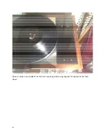
Page 8: ...Above custom Linn Sondek LP 12 tone arm mounting board using magnets for alignment and hold down 8...

Page 9: ...rod To adjust the position of the counterweight loosen the blue thumb nut in the direction that the counterweight should move and then rotate the other blue thumb nut in the same direction to again sn...

Page 10: ...ol insures that the stylus will be standing up perfectly straight when attached to the cartridge mounting pad Less than perfect vertical could be the result of either the front tower s elevator or the...

Page 11: ...Xacto knife or sharp shipping carton knife work as well Insert the two black nylon screws thru the cartridge mounting holes and hand tighten both screws as much as possible onto the cartridge cartridg...

Page 12: ...t overhang position of the cartridge mounting pad should the cartridge mounting pad be removed for cleaning etc After the stylus overhang position is finalized then use the M2 L wrench to gently turn...

Page 13: ...r is approximately 1 125 28mm above the plinth The elevators can rise above the towers as much as 75 19mm but should not be lowered below the tower top edge more than 125 3 175mm as the counterweight...

Page 14: ...owers the Plexiglas channel in minute increments An M6 aluminum bolt runs vertically thru each elevator part At the top of the aluminum bolt is a hex void where the elevator adjustment knobs can be in...

Page 15: ...bove the vinyl record just enough to clear the ridge at the LP outer rim The stylus drops a minimum vertical distance from above the LP Parallax is greatly minimized at the expense of being able to st...

Page 16: ...r of the punched hole and along the center of the strip of paper the length of the strip Mark two points on the line When the paper is on the spindle and lying on the mat one point should be near the...

Page 17: ...l mounting but handy for cuing Two stubs on a Wand finger lift 5 gr optional mounting but handy for cuing Two stubs on either side of the arch fit into the same two slots used to hold the cartridge mo...

Page 18: ...l bearing pressure can be set thru a hole in the outer gimbal It is best to set the horizontal bearing pressure before setting the vertical bearing pressure It is best to set the horizontal bearing pr...

Page 19: ...a Wand weights 1 Delrin Ladder cartridge mounting pad signal hat signal wires finger lift 18 gr 2 Delrin medallions 19...

Reviews: