background image

17

A-FRAME INSTALLATION

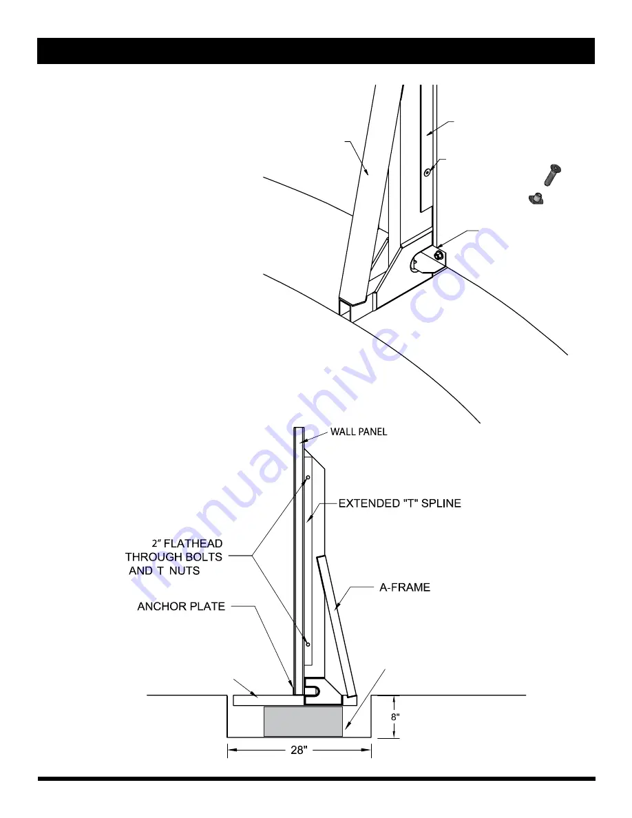
There are 8 A-frames per Freeform pool.  

The horizontal base of the A-frame will be under  
the wall panel and the A-frame anchor plate.   

The A-frame vertical will interlock inside the  
extended (T) splines at the wall connections.  
Secure A-frame to extended (T) splines with  
two (2) 2” flathead through bolts and T nuts.  
Do not over tighten.

2” Flathead Through 

   Bolt & T Nut

Extended T Spline

Anchor

Plate

A-Frame

Position hold down plates so that A-frame horizontal is  
covered in the interior of the pool. Pre-drill holes and then  
attach to horizontal using the sheet metal screws included.

TRENCH 
w/CONCRETE BLOCK

EARTH

POOL INTERIOR

A-FRAME HORIZONTAL

Summary of Contents for Metric Freeform

Page 1: ...Installation Manual Metric Freeform Residential Swimming Pool...

Page 2: ...e the gate is always closed Be sure to follow local building code requirements for load capacity and fencing if using an aftermarket or homebuilt deck 7 Check with your local town or municipality in r...

Page 3: ...ailer for replacement While all Radiant pools are designed to meet or exceed industry recommended safety standards ANSI APSP 4 and 5 American National Standards for Residential Inground Swimming Pools...

Page 4: ...ench Screwdrivers Flathead and Phillips 14 Channel Locks PVC Pipe Cutter Metal File Utility Knife Rubber Mallet Square Hacksaw Power Drill Shop Vac Wheelbarrow Extension Cord Masonry Sand 5 16 Hex nut...

Page 5: ...52J14 1 1 FREEFORM STURCTURAL BRACE KIT A FRAME COVER KIT set of 8 1 1 1 COPING KIT 1 1 1 SKIMMER AND ADAPTER KIT 1 1 1 LINER 1 1 1 REQUIRED COMPONENTS NOT INCLUDED IN POOL KIT 2 x 8 x 16 PATIO BLOCK...

Page 6: ...ment to radius wall panels 7 A Frames Extended Splines imbedded in concrete for stability 8 Panel Connector 9 Standard Splines Used at curved panel joints to join walls together 10 Hold Down Plates re...

Page 7: ...impact of heavy rain and high ground water conditions 4 When installing your pool on a solid level surface it is imperative that you protect your pool and liner from chemicals and other foreign matter...

Page 8: ...16x27 18x32 5 Remove lawn template 6 Mark a line 14 inside and outside of the pool outline from trench end to trench end 7 Level ground of pool outline include over dig of 12 at ends of pool 8 Dig tre...

Page 9: ...YOUT NO TEMPLATE POOL LAYOUT 1 Establish pool footprint with A B C D Rectangle example 14 x 22 2 Find points E F G H J and K 3 Swing arcs from these points to create and paint an outline of the pool 1...

Page 10: ...YOUT NO TEMPLATE 16 x 27 E A B C D H J K F G A B C D E F G H J K A B C D E F G H J A B C D E F G H J K A B C D E F G H J E A B A B C D E F G H J K A B C D E F G H J E A B C D H K F G J 18 X 32 LAYOUT...

Page 11: ...are 28 wide 5 Level ground within pool outline include overdig of 12 at both ends of pool Keep points H J and K secure 6 Dig trench areas 8 height of cinder block below bottom of pool grade 1 1 Bench...

Page 12: ...e they cross This is the mid line 2 From the mid line measure and mark a point on the pool outline 2 toward the pool bump Do this on both ends of the pool This will be the center of patio blocks 1 3 F...

Page 13: ...point on the pool outline 1 8 5 8 toward the pool indent Do this on both ends of the pool This will be the center of patio blocks 1 3 From the center of patio block 1 measure and mark a point on the...

Page 14: ...point on the pool outline 2 7 8 toward the pool indent Do this on both ends of the pool This will be the center of patio blocks 1 3 From the center of patio block 1 measure and mark a point on the po...

Page 15: ...es NOTE If wall panels are not level it will be hard to drop splines Use cooking oil or food spray as lubricant on the first 4 6 of the splines Do NOT use petroleum based lubricants WD 40 Hard downwar...

Page 16: ...securing the first reverse panel to the straight panel connector 6 Repeat step 2 securing the A frame anchor plate to the first reverse panel 7 In this step the panel will vary The bump will use a sta...

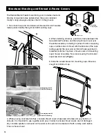
Page 17: ...wall connections Secure A frame to extended T splines with two 2 2 flathead through bolts and T nuts Do not over tighten 2 Flathead Through Bolt T Nut Extended T Spline Anchor Plate A Frame Position h...

Page 18: ...NTS 18 X 32 16 X 27 14 X 22 IMPORTANT Pool must be squared up BEFORE concrete is poured Measurements are taken from the inside of the pool wall When measuring to an A frame location hold tape at the m...

Page 19: ...Position mounting cups on either side of shroud with the flat side of the cups resting against the pool wall so that all holes punched in materials A frame T splines shroud cover and mounting cups li...

Page 20: ...yds 70 33 cu ft 1 2 x 2 4 x 10 6 28 6 cu ft 18 x 32 1 2 x 2 4 x 19 2 52 2 cu ft 3 5 yds 81 8 cu ft CONCRETE REQUIREMENTS CONCRETE IN TRENCH EARTH 12 Check level plumb and square of pool one final time...

Page 21: ...masonry sand per pool as shown in the chart below will provide a 2 layer across the pool floor and a 4 cove up the wall of the pool Pool Size Amount of Sand 14 x 22 16 x 27 2 5 yds 3 5 yds 4 5 yds 18...

Page 22: ...g E Use the fifth bolt and T nut at the bottom center hole in the mounting assembly and tighten firmly Do not over tighten Fig F Slip skimmer body through the white plate to the gasket on the gray pla...

Page 23: ...KIPPED Using a 1 8 drill bit drill through the plastic coping and EXTERIOR pool wall while pressing down firmly on the coping on top of pool wall Using a Phillips screw driver hand tighten each screw...

Page 24: ...and Liner Guides on next page Place the liner into the pool while holding onto the top of the wall section of the liner Snap the bead of the liner into the bead receiver track in the coping around the...

Page 25: ...25 COPING AND LINER GUIDES Drawings are for illustrative purposes and are not to scale 18 X 32 16 X 27 14 X 22...

Page 26: ...ighten each screw by a half turn alternating between each until all are tightened evenly This ensures uniform compression of sealing gaskets Using a razor knife carefully trim the liner from inside of...

Page 27: ...27 Metric Freeform Inground Installation Instructions...

Page 28: ...sturbed soil Since the excavation will be 2 feet wider than the actual pool dimension it is important that the excavator does not dig the 2 ft ledge around the hopper too deep NOTE A 2 ft excavation i...

Page 29: ...p of coping with top of step and plumb by checking front face of step unit with adjoining panel See images below to determine the proper benchmark for your installation Once step is positioned check l...

Page 30: ...exterior side of pool 3 8 carriage bolts and nuts backer washers 2 A frames for connection to T splines on either side of step Assemble the stair adapter kit to the first pool panel with the standard...

Page 31: ...e pool cutting the last length to fit Important When all lengths are installed apply a barrier between the bottom of the coping and the top of the pool wall to prevent sand and debris from getting in...

Page 32: ...ts are in place screw in securely Do not over tighten Install Skimmer Support It is recommended that 2 Schedule 40 PVC pipe be cut to size depending on installation Plug unused skimmer port Place PVC...

Page 33: ...ire pool if any point of the pool wall is 26 or greater in the ground fig 2 An example of a semi inground pool requiring a concrete collar is shown below fig 1 When installing an inground thermoplasti...

Page 34: ...corporating a French drain concept using a perforated drain pipe and water relief area away from the pool and other structures Backfill as the pool is filling with water manually compacting every 8 12...

Page 35: ...NOTES...

Page 36: ...36 440 North Pearl Street Albany NY 12207 1 800 RADIANT www radiantpools com 3 2016...

Reviews: