background image


Radiant, Inc. 


CONNECTION INSTRUCTIONS 
 

Connecting the DVMD to a camera and computer is a simple process.  The connections should 
be accomplished in the sequence outlined below. 


Step One: 


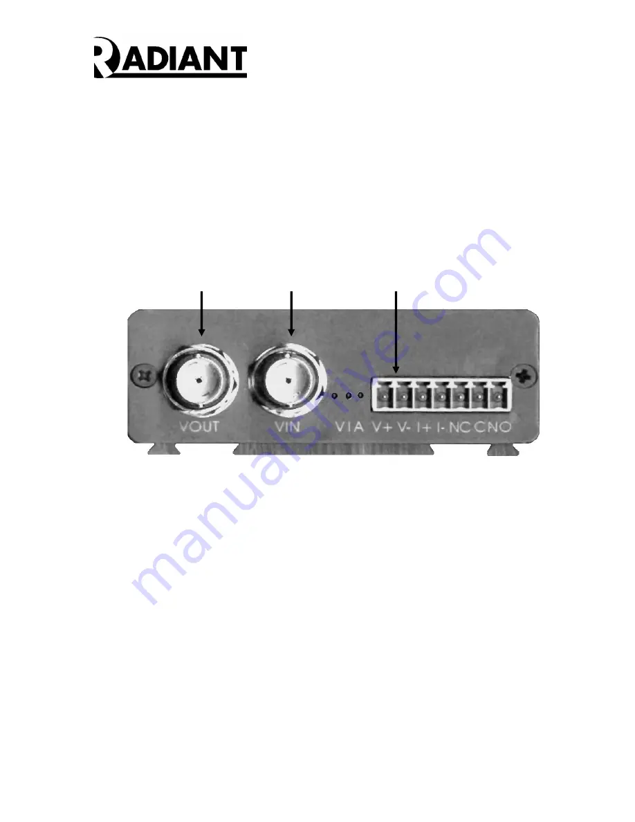
Connect  the  +12  VDC  Power  Supply  by  attaching  the  positive  supply  output  to  V+  and 
ground  to  V-.    These  screw  connectors  are  located  on  the  Front  Panel  of  the  DVMD-X 
(See Figure 4). 


Figure 4 – DVMD Front Panel 


Step Two:


Connect a 75 ohm Coaxial Cable from the VOUT BNC connector located on the DVMD 
Front Panel (See Figure 3) to the Video In port on a CCTV Monitor. 


Step Three:


Connect  a  second  75  ohm  Coaxial  Cable  from  the  VIN  BNC  connector  on  the  DVMD 
Front Panel (See Figure 3) to the Video Out port on a camera. 


Step Four:


Connect the NETWORK connector (See Figure 5) to a HUB/Router with a CAT5 Cable, 
or  to  the  NIC  card  in  the  PC  using  a  crossover  cable.    The  Green  LED  should  light  up 
when the network connection is established. 

Step 1 

V+ Connection


Step 2 

Video Out


Step 3 

Video In


Summary of Contents for DVMD1-X

Page 1: ...Hardware User s Manual Digital Video Motion Detector DVMD1 X Version 010 Revision A July 2004 Radiant Inc 2395 Kenwood Drive Boulder CO 80303 303 543 0440...

Page 2: ...MD1 X in a system Please also refer to the XPORT User Manual to change the IP address and Local Port number for each DVMD1 X The minimum DVMD1 X configuration must contain At least one DVMD1 X and Pow...

Page 3: ...ed to other DVDM1s through the CHAIN cable Each subsequent DVMD1 must be assigned a unique address on the rotary switch The address of the DVMD1 X is always set to FF0 Setting up the addresses is cove...

Page 4: ...T to the DVMD1 X DVMD FF0 VIDEO MONITOR VIDEO CAMERA 12 VDC POWER SUPPLY USER ALARM PANEL HOST COMPUTER Figure 2B DVMD1 X Connected to Host Computer Figure 1C illustrates a block diagram of three DVMD...

Page 5: ...wer opto isolated input and dry contact relay alarm output The opto isolated input is active when driven from an external voltage source between 4 to 24 volts The function of the opto isolated input i...

Page 6: ...port connections are made with an RJ12 connector crimped on a 6 wire phone cord Buy Digikey H2442 25 for short runs up to 25 feet Intermediate runs to 100 feet need 1 Digikey part number A9118 100 pc...

Page 7: ...nt Panel Step Two Connect a 75 ohm Coaxial Cable from the VOUT BNC connector located on the DVMD Front Panel See Figure 3 to the Video In port on a CCTV Monitor Step Three Connect a second 75 ohm Coax...

Page 8: ...check Steps 1 6 above If you do get a video image on the monitor proceed with loading the User Interface Software as described in the User Interface Manager Tools Window paragraph below If the power t...

Page 9: ...Radiant Inc 9 DVMD1 X PTZ JUMPERS Figure 6 below shows the DVMD1 X PCB and identifies the PTZ Jumpers as shipped Figure 6 DVMD1 X Enable Jumper...

Reviews: