background image


Radiant, Inc. 


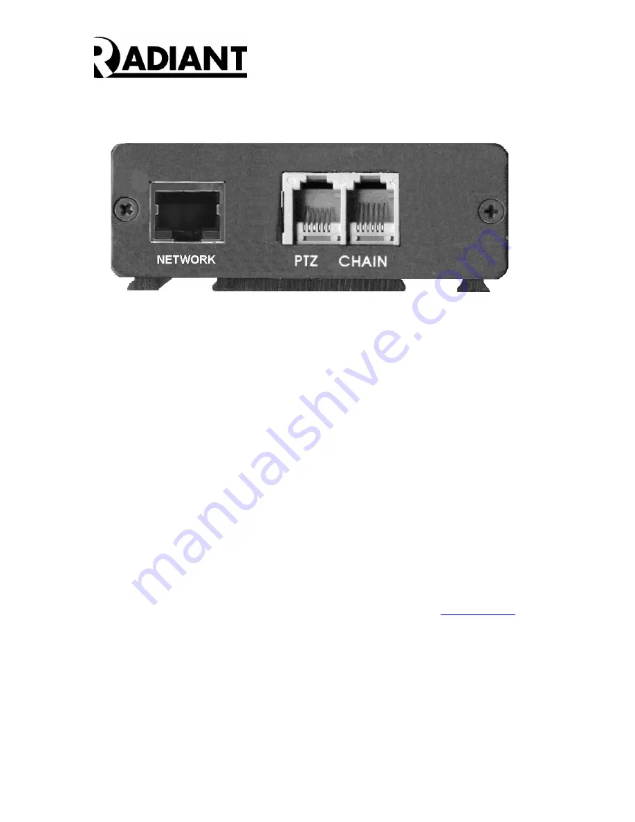
Figure 5 – DVMD1-X Rev B Rear Panel 


Step Five:


The  Unit  Address  is  internally  set  to  FF0  for  the  DVMD1-X  so  there  is  no  rotary  switch 
The RS485 CHAIN is internally terminated so there is no TERM switch on the DVMD-X. 
All  other  DVMD1-X  termination  switches  should  NOT  be  terminated.    A  six-conductor 
phone wire may be used to connect from the CHAIN output of the first unit (FF0) to the 
next unit. 


Power  up  the  camera,  the  CCTV  monitor  and  the  DVMDs.    You  should  get  a  video 
picture with overlay on the monitor.  If you do not get a picture on the monitor re-check 
Steps 1 – 6 above.  If you do get a video image on the monitor, proceed with loading the 
User  Interface  Software  as  described  in  the  User  Interface  –  Manager  Tools  Window 
paragraph below. 
 
If the power to  the DVMD  is off, the  video from the camera is connected  directly  to the 
CCTV monitor through an internal video bypass relay.  In the power off state, no DVMD 
functions occur, and no overlay is generated.   


User Interface – Manager 
 

You  may  download  the  most  recent  firmware  and  software  at 

www.dvmd.com

.  The 

ManagerNET.exe

 program provides the user interface to the DVMD.  Please refer to the 

DVMD Software User’s Manual for further information. 


XPORT User Manual 


Please  also  refer  to  the  XPORT  User  Manual  to  change  the  IP  address  and  Local  Port 
number for each DVMD1-X. 
 

Summary of Contents for DVMD1-X

Page 1: ...Hardware User s Manual Digital Video Motion Detector DVMD1 X Version 010 Revision A July 2004 Radiant Inc 2395 Kenwood Drive Boulder CO 80303 303 543 0440...

Page 2: ...MD1 X in a system Please also refer to the XPORT User Manual to change the IP address and Local Port number for each DVMD1 X The minimum DVMD1 X configuration must contain At least one DVMD1 X and Pow...

Page 3: ...ed to other DVDM1s through the CHAIN cable Each subsequent DVMD1 must be assigned a unique address on the rotary switch The address of the DVMD1 X is always set to FF0 Setting up the addresses is cove...

Page 4: ...T to the DVMD1 X DVMD FF0 VIDEO MONITOR VIDEO CAMERA 12 VDC POWER SUPPLY USER ALARM PANEL HOST COMPUTER Figure 2B DVMD1 X Connected to Host Computer Figure 1C illustrates a block diagram of three DVMD...

Page 5: ...wer opto isolated input and dry contact relay alarm output The opto isolated input is active when driven from an external voltage source between 4 to 24 volts The function of the opto isolated input i...

Page 6: ...port connections are made with an RJ12 connector crimped on a 6 wire phone cord Buy Digikey H2442 25 for short runs up to 25 feet Intermediate runs to 100 feet need 1 Digikey part number A9118 100 pc...

Page 7: ...nt Panel Step Two Connect a 75 ohm Coaxial Cable from the VOUT BNC connector located on the DVMD Front Panel See Figure 3 to the Video In port on a CCTV Monitor Step Three Connect a second 75 ohm Coax...

Page 8: ...check Steps 1 6 above If you do get a video image on the monitor proceed with loading the User Interface Software as described in the User Interface Manager Tools Window paragraph below If the power t...

Page 9: ...Radiant Inc 9 DVMD1 X PTZ JUMPERS Figure 6 below shows the DVMD1 X PCB and identifies the PTZ Jumpers as shipped Figure 6 DVMD1 X Enable Jumper...

Reviews: