27
HL2-DS
Series
3.0
Installation
•
Thermostat Connection
•
Thermostat Location
NOTE:
Different thermostats operate according to their particular features. Refer to thermostat
specifications for details.
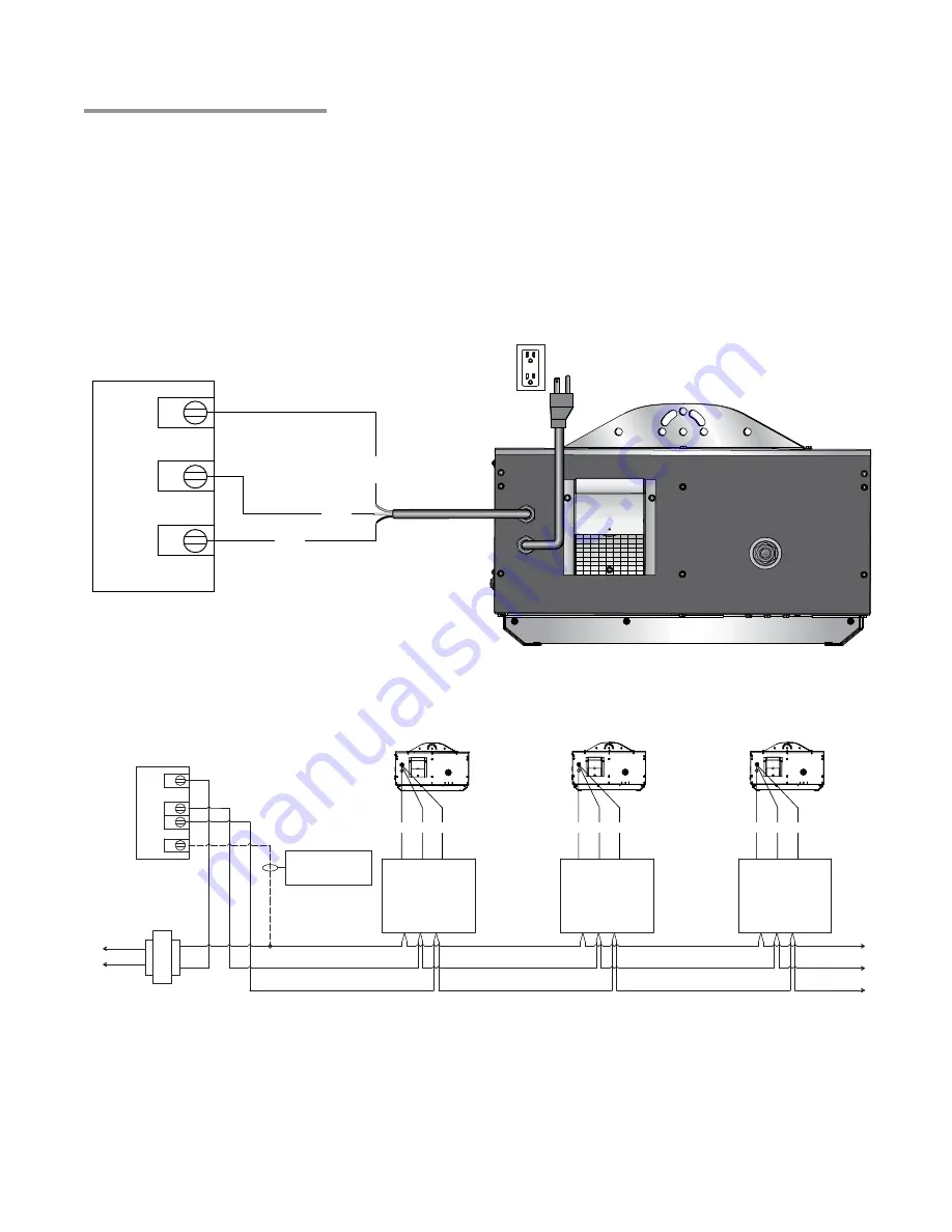
HL2-DS series heaters may be controlled by a thermostat or switch. The control voltage is 24 VAC and
the burner control box is equipped with a 60” yellow 24 VAC control wire. Do not supply 120 VAC to the
24 VAC connection.
Thermostat Connection
CONTROL DEVICE
TYP. TWO STAGE T-STAT OR
SWITCH
RELAY BOX
(1 PER HEATER)
W2
W1
R
C
TRANSFORMER
L1
L2
P/N: ERK
C
W1 W2
RELAY BOX
(1 PER HEATER)
P/N: ERK
C
W1 W2
RELAY BOX
(1 PER HEATER)
P/N: ERK
C
W1 W2
OPTIONAL 24V COMMON
CHECK THERMOSTAT
INSTRUCTIONS TO SEE
IF NEEDED
24V
120V
G
W
B
G
W
B
G
W
B
Field Wiring:
1
When controlling multiple heaters with a single control device, one ERK or ERK-HE per heater is
required.
2
An external 24 VAC transformer (.2 Amp) per heater is required (supplied by installer).
3
Maintain electrical polarity when hooking up multiple heaters.
4
Allow heaters to be switched by zones for heating flexibility.
5
Do not attempt to install transformer inside of heater.
Figure 3.17
•
Field Wiring Diagram -
Controlling multiple heaters with a single control device
Starting Amp Draw:
4.8 Amps
Running Amp Draw:
1.1 Amps
Figure 3.16
•
Field Wiring Diagram -
Controlling a single heater with a single control device
Starting Amp Draw:
4.8 Amps
Running Amp Draw:
1.1 Amps
R
W1
W2
CONTROL DEVICE
TYP. TWO-STAGE T-STAT OR
SWITCH
G
W
B


