background image

P1520 User Guide 

Version 1.2 

11

 04/02/07


Setting Up the P1520 

In order to begin using the P1520 for your POS operations, you must first set up various standard and peripheral 
components, including connecting the power source, connecting the P1520 to your network, and connecting any 
necessary peripheral devices.  This section outlines these setup processes.  

Note:  After all connections have been made, always close the Cable Management System to secure 

the cables and prevent accidental disconnects.  In addition, close the bottom cover after service or installation to 
provide protection for the user and prevent contaminants from entering the connectors. 

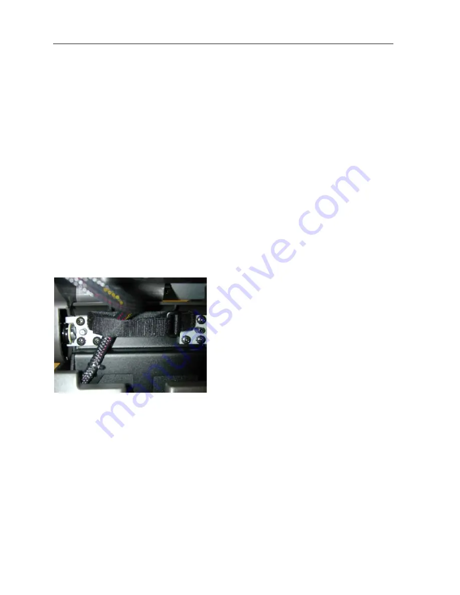
Cable Management System 

The Cable Management System is an innovative feature on the P1520 that provides for ease of installation, 
controlled access to connectors, concealed cable routing, and cable restraint for better reliability.   
 
Note:  After all connections have been made, always close the Cable Management System to secure the cables 
and prevent accidental disconnects.  In addition, close the bottom cover after service or installation to provide 
protection for the user and prevent contaminants from entering the connectors. 


1.


Tilt touch head back 

2.


Open Cable Management System strap 

3.


Plug cables in the input/output connectors 

4.


Route cables in cable clamp and close clamp 

5.


Close bottom door and tilt unit to user operating position 


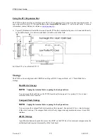
Connectivity (I/O) panel 

The P1520 offers very high connectivity including 6 RS232, 3 USB, 2 Direct Drive Cash Drawer ports, 2 PS/2 
ports, and a parallel port.  See Figure 2-1 below for bottom panel details. 

 
Picture 2-1 – 

P1520 Bottom Panel 


Summary of Contents for P1520

Page 1: ...Version 1 2 i 04 02 07 Radiant Model P1520 POS Terminal User Guide V1 2...

Page 2: ...e The official product name is P1520 Point of Sale and offers multiple configurations depending on operating system memory touchscreen motion sensor or storage configurations It is designed as a refer...

Page 3: ...1 Terminal Model Number Labels 12 Operating Systems 12 Connecting the Power Source 12 Connecting to a Network 12 Connecting Peripheral Devices 12 Using the RS 232 Ports 13 Using the USB Ports 14 Using...

Page 4: ...22 Important Safety Warning For Coin Battery Replacement and Handling 23 5 P1520 Device Drivers 23 General P15xx Configuration and Settings 23 P15xx dvOCD C500 P704Fxxx Software Developers Kit SDK 25...

Page 5: ...ssible display quality with excellent contrast and brightness Additionally the P1520 provides the very best in retail multimedia including full motion video The resistive touch screen provides a very...

Page 6: ...trast and color depth Enables the proper display of high quality graphics to ease use and decrease training time for retail employees or to directly engage the consumer Software adjustable brightness...

Page 7: ...d serviceable Model P1520 Optional Features Operating System Options See configuration options Microsoft Windows XP Professional Operating System Microsoft Windows XP Embedded Operating System Storage...

Page 8: ...it Feature Number P150F020 Kit includes back door and hinges for mounting advertising displays to top back of terminal USB Keyboard with four USB ports Feature Number KB00001 The USB keyboard offers 1...

Page 9: ...ble with the tilt base configuration For more information on powered USB see http www poweredusb org Specifications CPU Intel Celeron M 900Mhz or 1 3Ghz or Pentium M 1 6GHz processor or higher Volatil...

Page 10: ...ional With Third Party Application Software The P1520 will boot to the operating system or directly to the third party application Cable Restraint The P1520 includes a cable management system with cab...

Page 11: ...nting options included countertop wall mount and keyboard tray In addition we can lock the terminal using a laptop locking cable See below for bolt pattern Wall Mount Installation P762F004 1 Tilt Brac...

Page 12: ...from P15xx base located in the cable channel 5 Place P15xx on wall mount bracket aligning 4 hang tabs with 4 slots on bottom of P15xx base 6 Secure the P15xx to wall mount by replacing machine screw r...

Page 13: ...nnovative feature on the P1520 that provides for ease of installation controlled access to connectors concealed cable routing and cable restraint for better reliability Note After all connections have...

Page 14: ...Connecting to a Network Most business configurations will require you to connect your P1520 system to a network Connecting to a network will enable you to communicate with other systems and devices al...

Page 15: ...rts Please refer to each device s User Manual to determine which type of port it supports To connect a peripheral device to one of the RS 232 serial ports on the P1520 plug the device cord into any of...

Page 16: ...r Ports The P1520 can power two different type cash drawers direct drive or serial The terminal has two direct drive cash drawer ports with RJ11 4 pin connectors labeled 1 and 2 on the bottom I O pane...

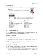
Page 17: ...P1520 can be configured with USB Disk on Chip uDOC Compact Flash or 3 5 Hard Disk Drive storage Hard Drive Storage NOTE Unplug the terminal before opening the back panel door You can access the hard...

Page 18: ...ashing yellow 3 Using the P1520 The P1520 platform functions as a POS terminal for your business Performance and functionality will differ according to the operating system software and peripheral dev...

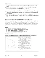
Page 19: ...ptional Mylar Overlay on the P1520 Resistive Touchscreens Resistive touch screens wear over time as do other input devices such as keypads and keyboards To preserve the touch screen Radiant offers a t...

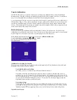
Page 20: ...contact touch screen sense it could damage the touch sensing layer With a Radiant application from the managers menu select calibrate touchscreen From the desktop or startup menu run type tcalib You c...

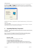
Page 21: ...d then clean the touchscreen 4 Upgrading Replacing Components Warning Upgrading and replacing parts will be done by trained Service Personnel only Below are the instruction for upgrading and replacing...

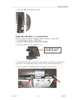
Page 22: ...via software or On Off button 2 Important UNPLUG power cord from wall or terminal 3 Remove the back panel cover 2 phillips screws 4 Disconnect hard drive power and hard drive data connectors see figu...

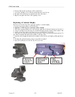
Page 23: ...m terminal connection at bottom of terminal see Figure 2 1 4 Unscrew 2 phillips screws from top cover while holding the customer display so that it doesn t fall 5 Gently pull customer display module a...

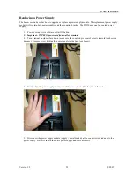
Page 24: ...ftware or On Off button 2 Important UNPLUG power cord from wall or terminal 3 Turn terminal on side or face down make sure the countertop is clear of objects to avoid touch screen damage Remove screw...

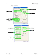
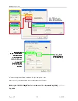
Page 25: ...structions 5 P1520 Device Drivers Below is a list of drivers on the P1520 To view the P15xx Configurations and Settings interface go Start Control Panel P15xx Hardware Also please see instruction file...

Page 26: ...ve Touch Screen Platform Model Platform Model Unit Serial Number Unit Serial Number BIOS Version BIOS Version Primary Backlight Primary Backlight System Counters System Counters Screen Touch Counters...

Page 27: ...Note MSR Keyboard Wedge Service needs to be stopped for OPOS test MSR Keyboard Wedge service Status Stopped OPOS Started Keyboard Test with Notepad MSR Keyboard Wedge service Status Stopped OPOS Star...

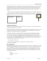
Page 28: ...ter should be set to 0 for the main screen and to 1 for the dvOCD It is possible during runtime to determine if the dvOCD screen is plugged in and recognized by querying Windows for the screen size Th...

Page 29: ...520 Follow these steps to replace a P1520 1 Locate the unit to be serviced 2 Properly shut down the terminal through either the software application operating system or by using the On Off button on t...

Page 30: ...e radio frequency energy and if not installed and use in accordance with the instruction manual may cause harmful interference to radio communications Operation of this equipment in a residential area...

Page 31: ...P1520 User Guide Version 1 2 29 04 02 07...

Page 32: ...e terminal to the source usually a power strip or a battery backup and verify power there d If power is good at the source but still not at the touch head try swapping out the power cable from another...

Page 33: ...ucts These cables have a half twist so that all outbound signals will automatically be routed to the appropriate inputs on the other side RJ ports are the ones using the standard telecom modular plugs...

Page 34: ...ed 3M Touch Controllers and Touch Glass The driver package covered in this document is the following 3M Version 5 64SR4 with RUNME bat script 5 64_SR4 zip Radiant custom un install install script RUNM...

Page 35: ...the primary display to calibrate Check to see if the TouchWare Monitor shortcut was removed from the Startup folder If missing recreate the shortcut to MtsTsMon exe C PROGRA 1 MICROT 1 TOUCHW 1 MtsTs...

Reviews: