26
R1K 34 /B - RAD - ING - Manuale - 1512.2_CSA_TTS
1. INSTALLATION
INST
ALLER
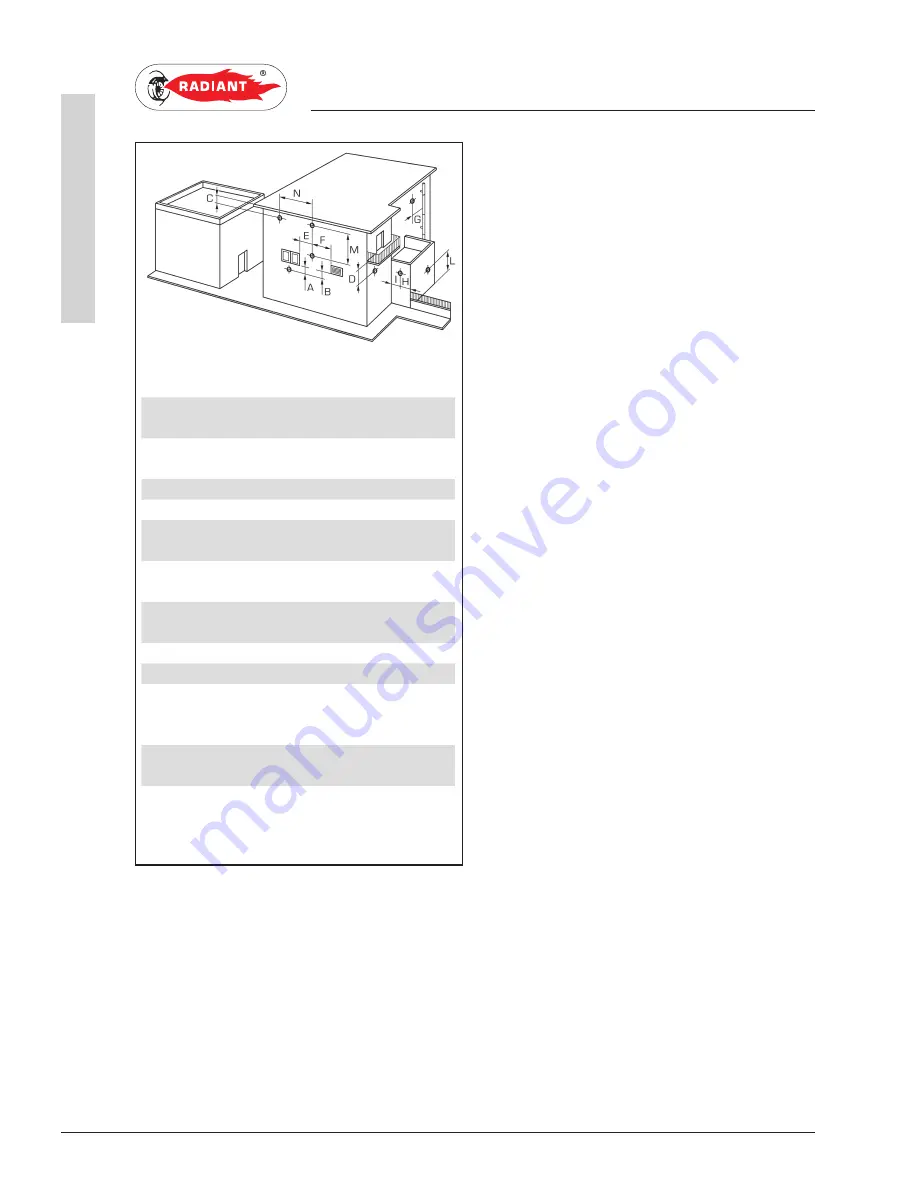
TABLE MINIMUM DISTANCE
feet mm
A- below openable window or
door
3*
900*
B- below ventilation opening
(non mechanical)
3*
900*
C- below soffits
1
300
D- below balcony
1
300
E- from adjacent window or
door
3*
900*
F- from adjacent ventilation
opening (non mechanical)
3*
900*
G- from horizontal or vertical
soil or drain pipes
1
300
H- from corner of building
1
300
I - from recess in building
1
300
L - above a paved sidwalk or a
paved driveway that is located
on public property
7
2100
M- between two terminals set
vertically
2
600
N- between two terminals set
horizontally
2
600
(*)- FOR APPLIANCE WITH INPUTS UP TO
AND INCLUDING 100,000 Btu/h (29.3 kW) THIS
DISTANCE REDUCES TO 1 ft (300 mm).
1. The vent shall not terminate:
a) where it may cause hazardons frost or ice
accumulations on adjacent property surfaces;
b) less that 7 ft (2.1 m) above a paved sidewalk or a
paved driveway that is located on public property;
c) within 6 ft (1.8 m) of a mechanical air-supply
inlet to any building;
d) above a regulator within 3 ft (900 mm) horizontally
of the vertical centerline of the regulator vent outlet
to a maximum vertical distance of 15 ft (4.5 m);
e) within 3 ft (900 mm) of any gas service regulator
vent outlet;
f) less than 1 ft (300 mm) above grade level plus
expected snow level;
g) within the following distances of a window or
door that can be opened in any building, of any
non-mechanical air supply inlet to any building, or
of any combustion air inlet of any other appliance;
· i) 12 in (300 mm) for inputs up to and including
100,000Btu/h.
· ii) 3 ft (900 mm) for inputs exceeding 100,000
Btu/h.
h) Underneath a veranda, porch, or deck unless;
· i) the veranda, porch, or deck is fully open
on a minimum of two sides beneath the floor;
and
· ii) the distance between the top of the vent
termination and the underside of the veranda,
porch, or deck is greater than 1 ft (300 mm);
2. Building material within 5 ft (1,5m) of a vent
terminal will be subjected to products of combustion
and therefore may be subject to discoloration or
deterioration, of building materials.
INSTALLATION
fig. 18
Summary of Contents for R1K 34
Page 6: ......
Page 62: ......
Page 65: ...65 R1K 34 B RAD ING Manuale 1512 2_CSA_TTS 3 USE USER...
Page 66: ...66 R1K 34 B RAD ING Manuale 1512 2_CSA_TTS 3 USE USER...
Page 67: ...67 R1K 34 B RAD ING Manuale 1512 2_CSA_TTS 3 USE USER...
Page 68: ...68 R1K 34 B RAD ING Manuale 1512 2_CSA_TTS 3 USE USER...
Page 79: ......


