INSTALLATION INSTRUCTIONS
CONDENSING BOILOES WITH STORAGE - TG05A095.A0306
20
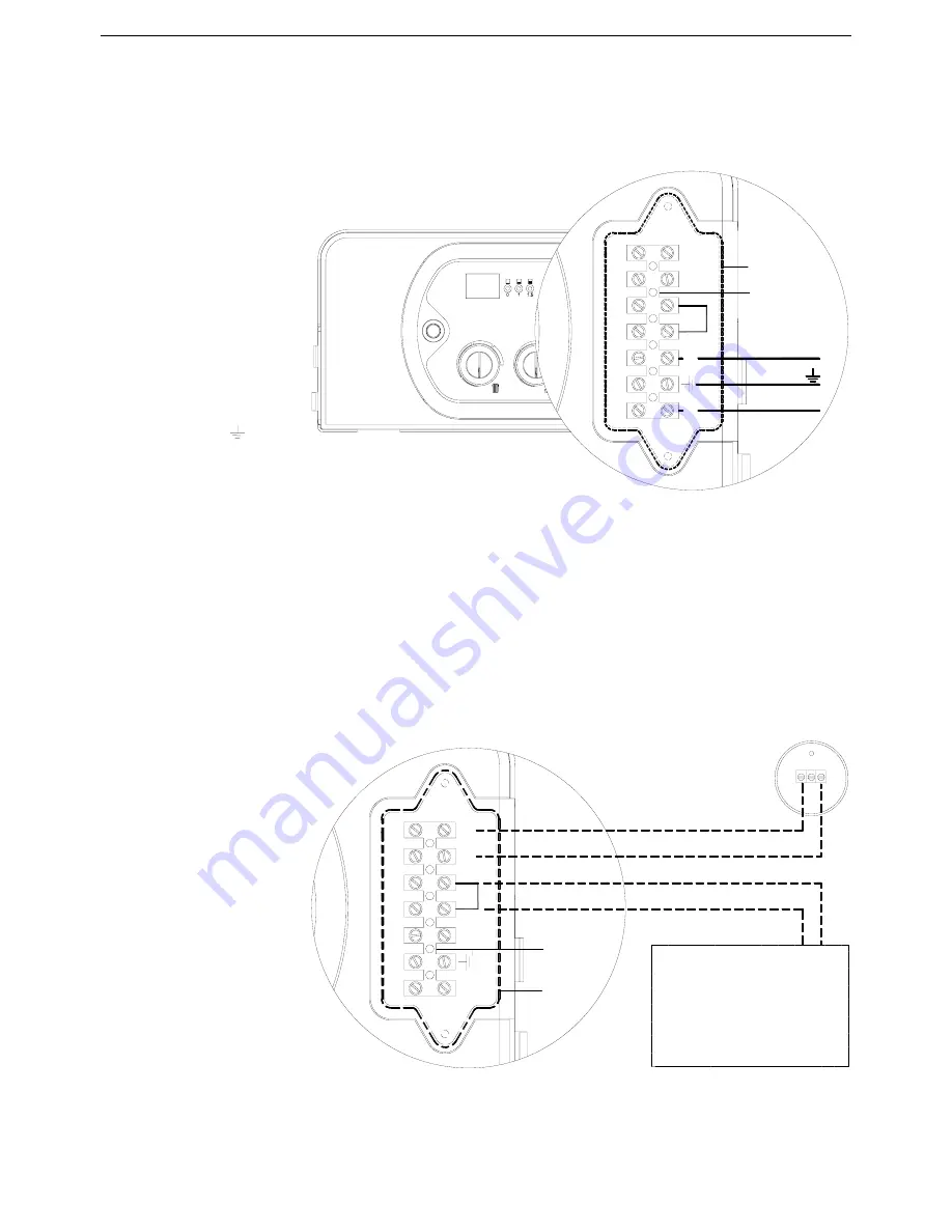
Electric power supply
Connect the power supply to the terminal board inside the control panel as follows:
a.
Switch off the power
supply at the main switch.
b.
Remove the front panel of
the boiler.
c.
Slacken the screws and
remove plate A (see fig.
1).
d.
With the plate removed,
connect the wires to the
terminal board B as
follows:
•
Connect the earth wire
(normally coloured
green/yellow) to the
terminal marked with the
earth symbol “ “.
•
Connect the neutral wire
(normally coloured blue)
to the terminal marked
with the letter “N”.
•
Connect the live wire (normally coloured brown) to the terminal marked with the letter “L”.
•
Terminals identified by the letters: Ta
⇒
Room thermostat
Se
⇒
Outdoor sensor
When the wires have been connected, replace plate “A" and then the front panel.
3.11 Connecting the room thermostat and outdoor sensor
please include the external temperature sensor part number.
Connect the wires to the
terminal board inside the
instrument panel as follows
(Example of WEEK digital
room thermostat/time):
a.
Switch off the power
supply at the main switch.
b.
Remove the front panel of
the boiler.
c.
Slacken the screws and
remove plate A (see fig.
2).
d.
Remove jumper TA-TA
from the terminal board.
e.
Connect the
thermostat/timer wires.
When the wires have been
connected, replace plate “
A
"
and then the front panel.
Fig. 1
Ta
LN
Ta
Se
Se
B
A
neutral
live
Ta
B
LN
Ta
Se
Se
1
M1
2
A
EXTERNAL SENSOR
THERMOSTAT/TIMER
Fig. 2
Summary of Contents for RKA 25
Page 2: ......


