INSTALLATION INSTRUCTIONS
10
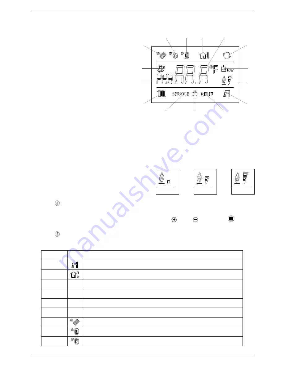
LCD DISPLAY ICONS’ KEY
1.
PARAMETER NUMBER INFORMATION
2.
PARAMETERS PROGRAMMING MODE ON
3.
SOLAR PCB CONNECTION INFORMATION /
SOLAR PANEL TEMPERATURE DISPLAY (d6)
4.
SOLAR PUMP ON
5.
STORAGE CYLINDER LOW LEVEL
TEMPERATURE VISUALIZATION (d7) /
STORAGE CYLINDER HIGH LEVEL
TEMPERATURE VISUALIZATION (d8)
6.
OUTDOOR TEMPERATURE SENSOR
CONNECTED / OUTDOOR SENSOR
TEMPERATURE DISPLAY (d2)
7.
TEMPERATURE / SET POINT / PARAMETER
VALUE INFORMATION
8.
OPEN THERM COMPONENTS
COMMUNICATION CONNECTED (REMOTE
CONTROL / ZONE MANAGEMENT CONTROL
BOX)
9.
WATER LOW PRESSURE INFORMATION
10.
(*) FLAME PRESENCE ON (3 POWER STEPS)
11.
D.H.W. MODE ENABLED
12.
RESETTABLE ERROR DISPLAY
13.
OFF MODE
14.
NOT RESETTABLE ERROR DISPLAY
15.
HEATING MODE ENABLED
10 (*) - During the boiler operation the display can show 3
different power levels according to the flame modulation
of the boiler. (see flame icon/power % images)
2.8 INFO Menu display
Press the ‘
’ INFO Button to display the boiler data.
Once pressed, the parameter number will appear on the left side of the display and the associated
parameter value will appear on the centre of the display. Use ‘
’ and ‘
’ buttons of
Heating
Temperature setting to scroll the list of available data.
Press the ‘
’ INFO button to exit the display mode.
The list of available display data is the following:
Parameter Icon
Description
d00
DHW sensor temperature
d01
Outdoor sensor temperature
d02
Kd
Thermoregulation value
d03
Fan speed
d04
Low temperature circuit sensor (only with Zone PCB connected)
d05
Heating return sensor temperature
d06
Solar panel sensor temperature (only with Solar PCB connected)
d07
Solar storage cylinder temperature (low level) (only with Solar PCB connected)
d08
Solar storage cylinder temperature (high level) (only with Solar PCB connected)
4
5
6
7
9
10
11
12
13
14
15
1
2
3
8
< 33%
>33%<66%
>66%<100%
Summary of Contents for RKA 34
Page 2: ......


