INSTALLATION INSTRUCTIONS
17
3.7 Condensate drain
FAILURE
TO
INSTALL
THE
CONDENSATE
DISCHARGE
PIPEWORK
CORRECTLY
WILL
AFFECT THE RELIABLE OPERATION OF THE
BOILER. The condensate discharge pipe MUST NOT
RISE at any point along its length. There MUST be a
fall of AT LEAST 2.5° (50mm per metre) along the
entire run.
CAREFUL ATTENTION IS REQUIRED TO MINIMISE
THE RISK OF FREEZING DURING PROLONGED
COLD SPELLS.
I. The boiler condensate outlet terminates in a 25 mm
flexible plastic pipe for connection to a plastic pipe
which should generally discharge internally into the
household drainage system. If this is not possible,
discharge into an outside drain or suitable soak-away is
acceptable.
2. Ensure the discharge of condensate complies with
any national or local regulations in force.
BS 6798:2000 & Part H I of the Building Regulations
give further guidance.
3. The discharge pipe should be run in a proprietary
drain pipe material e.g. PVC, PVC-U, ABS, PVC-C or
PP and take the shortest practicable route to a
termination point.
4. Metal pipe work is NOT suitable for use in
condensate discharge systems.
5. The pipe should be a minimum of 22 mm diameter
and must be supported using suitably spaced clips to
prevent sagging.
6. Any pipe fitted externally should not exceed 3
metres.
7 Any condensate discharge pipe work external to the
building (or in an unheated part of it e.g. garage) must
be insulated to protect against frost. It is also
recommended that the pipe diameter is increased to
32mm.
8. If the boiler is fitted in an unheated location the entire
condensate discharge pipe should be treated as an
external run.
9. In alI cases discharge pipe must be installed to aid
disposal of the condensate. To reduce the risk of
condensate being trapped or freezing, as few bends
and fittings as possible should be used.
10. When discharging condensate into a soil stack or
waste pipe the effects of existing plumbing must be
considered. If soil pipes or waste pipes are subjected to
internal pressure fluctuations when WC's are flushed or
sinks emptied then back-pressure may force water out
of the boiler trap and cause appliance lockout.
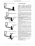
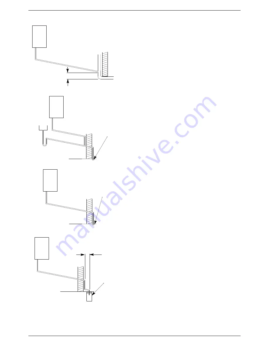
Examples are shown of the following methods of
termination:-
i) to an internal soil & vent pipe
ii) via an internal discharge branch (e.g. sink waste)
iii) to a drain or gully
iv) to a purpose made soak away
450mm min
Holes in the soak-away must
face away from the building
500mm min
External termination to a purpose made soak-away
External termination to a drain or gully
Pipe must terminate above
water level but below
surrounding surface
50mm pe
r metre of p
ipe run
2.5° Minim
um fall
50mm per
metre of p
ipe run
2.5° Minimu
m fall
Boiler
Pipe must terminate above
water level but below
surrounding surface
50mm per
metre of p
ipe run
2.5° Minimu
m fall
External termination via internal discharge
branch e.g. sink waste - downstream
Sink
2.5° Minim
um fall
50mm per
metre of p
ipe run
Termination to an internal soil and vent pipe
Boiler
Boiler
Boiler

