background image

Installation Manual  

Wall Hung Boiler with D.H.W. Storage Cylinder Low Nox – Cod. 99881NA – July 2001 


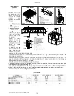
GAS CONNECTIONS 

The gas supply must be connected up by qualified person. 

The following standards must be complied with: UNICIG 7131/72 and UNICIG 7129/92 (of 21/04/93) 
Before installing the boiler, make sure of the following: 

• 

the pipeline must be of an adequate section and length to carry the flow required and must be fitted with all safety devices 
and measures prescribed by current norms; 

• 

before turning on the boiler make sure the type of gas which it is designed to run on is available  

• 

the gas supply pressure must lie within the values shown on the plate it is recommended that the gas supply pipeline should 
be checked for residual obstructions before installing the boiler; 

• 

where the internal gas supply pipe meets the boiler, a gas shutter cock must be fitted which has the same diameter as the 

gas inlet pipe; 

• 

check thoroughly that the gas inlets and outlets are properly sealed. 

• 

conversion to allow the boiler to run on LPG to natural gas or vice versa must be carried out by a qualified gas fitter in 

accordance with law no.46 of 5th March ‘90 (see p.18). 


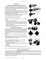
ANTI-FROST SYSTEM  

Radiant boilers are equipped with an Anti-Freeze system which comes into operation when the temperature falls to 5° C 

(Heating sensor) and 4° C (Hot water sensor) and protects the boiler down to –2°C external temperature.                                         

To protect the internal Radiators, a room thermostat or remote control must be fitted. 
 

NOTE: The frost system will only come into operation if the boiler is filled with water, and connected to a live gas supply, with 

electrical supply and boiler controls in the “ON” position (With the Main switch turned to Summer or Winter position) 

)  and the 

gas supply turned on. 


FOR THE INSTALLER 

For boilers installed outdoors, where the 

temperature may drop below -2° degrees 

Centigrade, the system should be filled 

with antifreeze liquid by an authorised 

technician and a set of electrical heating 
elements should be fitted to protect the 

domestic hot water heat exchanger. 


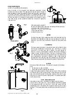
ADVICE FOR THE SERVICE 
TECHNICIAN 

If the boiler is out of service 

because it is frozen, check that 

no parts have been locked in 

position by ice before putting it 
into operation.  

It is advisable to empty the 

boiler and the system in case of 

no operation for a long period. 


Recommended percentage of 

glycol for temperatures down to 

- 8°C is 20%.

The antifreeze 

liquid used must be of a good 

make and in a solution which 

has already been diluted to 

avoid the risk of uncontrolled 

dilution.  


Table n°1 


Antifreeze Temperature 


Ethylene glycol  

(%) volume  

freezing point 

 (°C) 

boiling point   

 (°C) 

10 - 

4 101 

20 -10 102 
30 - 

17 104 

40 - 

27 106 

50 - 

40 109 

60 - 

47 114 

1

2

3

4

5

6

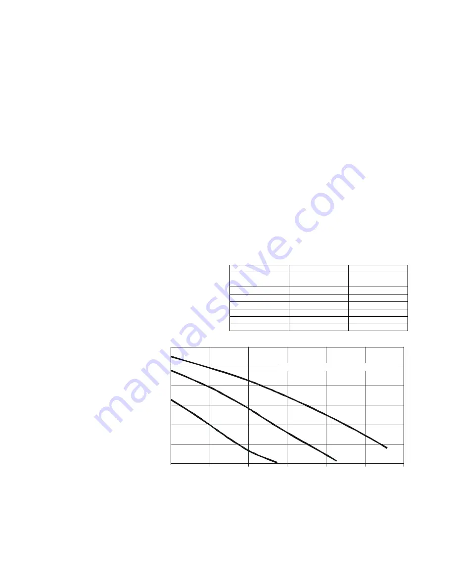
0

1000

500

2000

1500

3000

0

2500

P

re

va

len

za

: m.

c.

a.

Portata: l/h

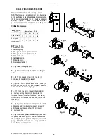
CIRCULATING PUMP SPECIFICATIONS 

Summary of Contents for RMA

Page 1: ...BRUCIATORI S p A Montelabbate PU ITALY By Technical Department INSTALLATION USE AND MAINTENANCE MANUAL FOR GAS FIRED WALL HUNG BOILERS WITH DOMESTIC HOT WATER STORAGE CYLINDER Model RMA TYPE B OPEN C...

Page 2: ......
Page 3: ...REQUIREMENTS page 6 BOILER INSTALLATION page 8 ELECTRICAL CONNECTIONS page 10 19 22 BOILER CONTROL PANEL page 11 STARTING UP THE BOILER FOR THE FIRST TIME page 11 BOILER ADJUSTMENTS page 13 MULTIGAS O...

Page 4: ...ADDING AN OPTIONAL TIMER SELF DIAGNOSTIC LEGEND see fig 2 6 OPERATING POWER INDICATOR 7 DOMESTIC HOT WATER OPERATION 8 HEATING OPERATION 9 FLASHING LIGHT DENOTING AIR PRESSURE SWITCH FAILURE 10 FLASH...

Page 5: ...re range can be adjusted from a minimum of 30 C to a maximum of 80 C REGULATING THE HOT WATER TEMPERATURE The hot water temperature is regulated by turning knob 4 see fig 1 pag I turn it counter clock...

Page 6: ...mogeneous highly functional unit that is easy to install and simple to operate The wall mounted boiler is equipped with all of the approved accessories required to make it a true independent heating p...

Page 7: ...ating unit has been constructed to heat the home and to produce hot water The constructor declines all responsibility for incorrect installation and or use of the device Do not leave the device on whe...

Page 8: ...KCal h 22950 23090 Kw 26 68 26 85 BTU h 91066 91621 Minimum rated output KCal h 12950 12900 Kw 15 06 15 BTU h 51386 51187 Heting temperature adjustment C 30 80 30 80 Max working pressure heating bar 3...

Page 9: ...ength by 0 8 m Kit B Double exhaust emission twin flue system with 360 rotation It allows the flue exhaust into a flue duct and the air intake directly from an external wall To insert a bend reduce to...

Page 10: ...ust fans into single chimney collective flues with natural draft or multiple combined flues follow the directions set out in the UNI 10640 standard CONNECTION OF FLUE PIPES All boilers must be connect...

Page 11: ...should ensure a nominal dynamic pressure of 20m Bar 8 in wg at the boiler Installation pipes should be fitted in accordance with BS6891 1988 Pipework from the meter to the boiler must be 22mm copper t...

Page 12: ...r sources of natural air infiltration or forced ventilation air conditioning systems If this should occur the appliance MUST BE TURNED OFF IMMEDIATELY and the local gas region consulted Where the lowe...

Page 13: ...nect pipes and valves as shown in the picture 5 Position the boiler paying attention to hang it to the hanging bracket do not lean the boiler on the JIG and make final connections WATER CONNECTIONS To...

Page 14: ...5 C Heating sensor and 4 C Hot water sensor and protects the boiler down to 2 C external temperature To protect the internal Radiators a room thermostat or remote control must be fitted NOTE The frost...

Page 15: ...d with the earth symbol see fig 3 connect the blue wire to the terminal marked with the letter N connect the brown wire to the terminal marked with the letter L CONNECTION OF ROOM THERMOSTAT NOTE use...

Page 16: ...s no sign of leaks in any case double check by using a soapy solution and eliminate all eventual leaks The checking procedure for the gas burner attachment is carried out with the boiler working make...

Page 17: ...ignition procedure press release button 2 see fig 1 pag 11 and then try the ignition procedure once again If the boiler does not start press the reset button 2 see fig 1 pag 11 IMPORTANT should the bo...

Page 18: ...crewdriver for any adjustments Turn clockwise to increase gas pressure to the burner at start up by setting the trimmer to maximum calibration pressure of modulator see page 16 Turn counter clockwise...

Page 19: ...to suit the type of gas used undo fixing nut 8 on the thin aluminium gas pipe 9 and change the jet g replace the gas setting plate that indicates the type of gas and nominal pressure for the boiler W...

Page 20: ...biliser Fig B Widen locking clips 2 Fig C Slide out the coil 1 located above the gas valve Fig D Tighten plastic screw 3 by turning it clockwise be careful not to break it Fig E Use a no 17 spanner to...

Page 21: ...hich when set on the top position towards the valve head allows the boiler operating on the domestic hot water circuit while when set on the low position the boiler operates on the central heating cir...

Page 22: ...ot water see fig 2 item B fig 3 It allows conversion to hot water even with a minimum hot water demand 2 litres min using an electromagnetic principle with electrical switching by means of a relay The...

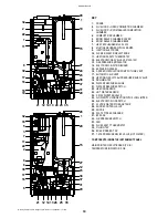
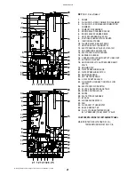
Page 23: ...AUTOMATIC AIR VENT 18 HEATING CIRCUIT 3 bar PRESSURE RELIEF VALVE 19 DRAINING TAP 20 WATER PRESSURE GAUGE 21 WATER PRESSURE SWITCH 22 HEATING SENSOR 23 HOT WATER SENSOR 24 3 WAY DIVERTER VALVE 25 FLOW...

Page 24: ...IR VENT 17 AUTOMATIC AIR VENT 18 HEATING CIRCUIT 3 bar PRESSURE RELIEF VALVE 19 DRAINING TAP 20 WATER PRESSURE GAUGE 21 WATER PRESSURE SWITCH 22 HEATING SENSOR 23 HOT WATER SENSOR 24 3 WAY DIVERTER VA...

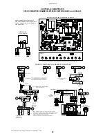
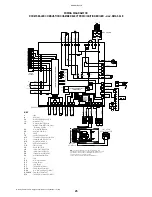
Page 25: ...5 LED6 RAVI II J2 D2 J3 FA1 C3 R48 C20 R49 R17 R23 R24 R47 R13 C8 J9 C6 C19 C21 C7 R15 R32 C13 R39 R37 R31 41 M9 R62 R61 R57 R16 42 C14 C9 R38 C5 RS1 J20 IC2 R18 IC1 R42 43 GPL 44 J7 46 45 R20 C12 R58...

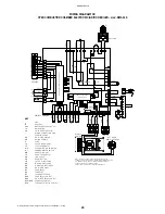
Page 26: ...5A 2019 4 PS 5 TS LB 7 6 9 9 8 11 11 10 10 12 12 8 13 EA ER 14 15 P 6 ELECTRONIC TEMPERATURE INDICATOR 54 50 51 53 52 55 56 58 57 RVB RVA RV 2 1 3 7 23 19 24 17 18 22 IG VD R CY CX L 20 5 21 16 4 NET...

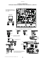
Page 27: ...F CONNECTORS 23 LED5 C6 C7 RS1 R58 R22 R21 4 2 1 3 15 14 22 LED2 LED1 LED3 LED4 RAVI II R31 42 R18 R17 yellow blue R48 FA1 C20 R49 R23 R24 R47 C19 C21 red brown R39 C9 M9 R62 R61 R57 J16 R38 C5 J20 R3...

Page 28: ...OSTAT FLOWSWITCH MICRO SWITCH M F TS HEATING SENSOR D H WATER SENSOR SR SS 3 WAY DIVERTOR VALVE WIRING CONNECTION ONLY FOR Mod VC6012 VD black black black black brown orange black black M F WATER PRES...

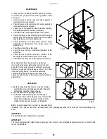
Page 29: ...water flow rate and temperature When dismantling the boiler casing be careful when removing the side panels after having removed the front panel the front panel is removed by undoing the lower and fr...

Page 30: ...g 1 on a replace it b re connect or replace it c replace it d change over polarity e make earth connection f fit conversion kit 4 Boiler on temperature rises rapidly and extinguishes flame light 2 fig...

Page 31: ...08LA 3 BAR PRESSURE RELIEF VALVE 1 2 16 96026LA D H W CYLINDER TEMPERATURE 90 PRESSURE 7BAR SAFETY VALVE 17 20030LA INSULATED 25 LT STORAGE CYLINDER 18 95006LA 10 LT EXPANSION TANK W BRACKET 19 96007L...

Page 32: ...6 Tel 39 0721 498822 Fax 39 0721 499815 Email tecnico radiant it italia radiant it export radiant it Internet http www radiant it All descriptions and illustrations contained in this leaflet have been...

Reviews: