background image

3

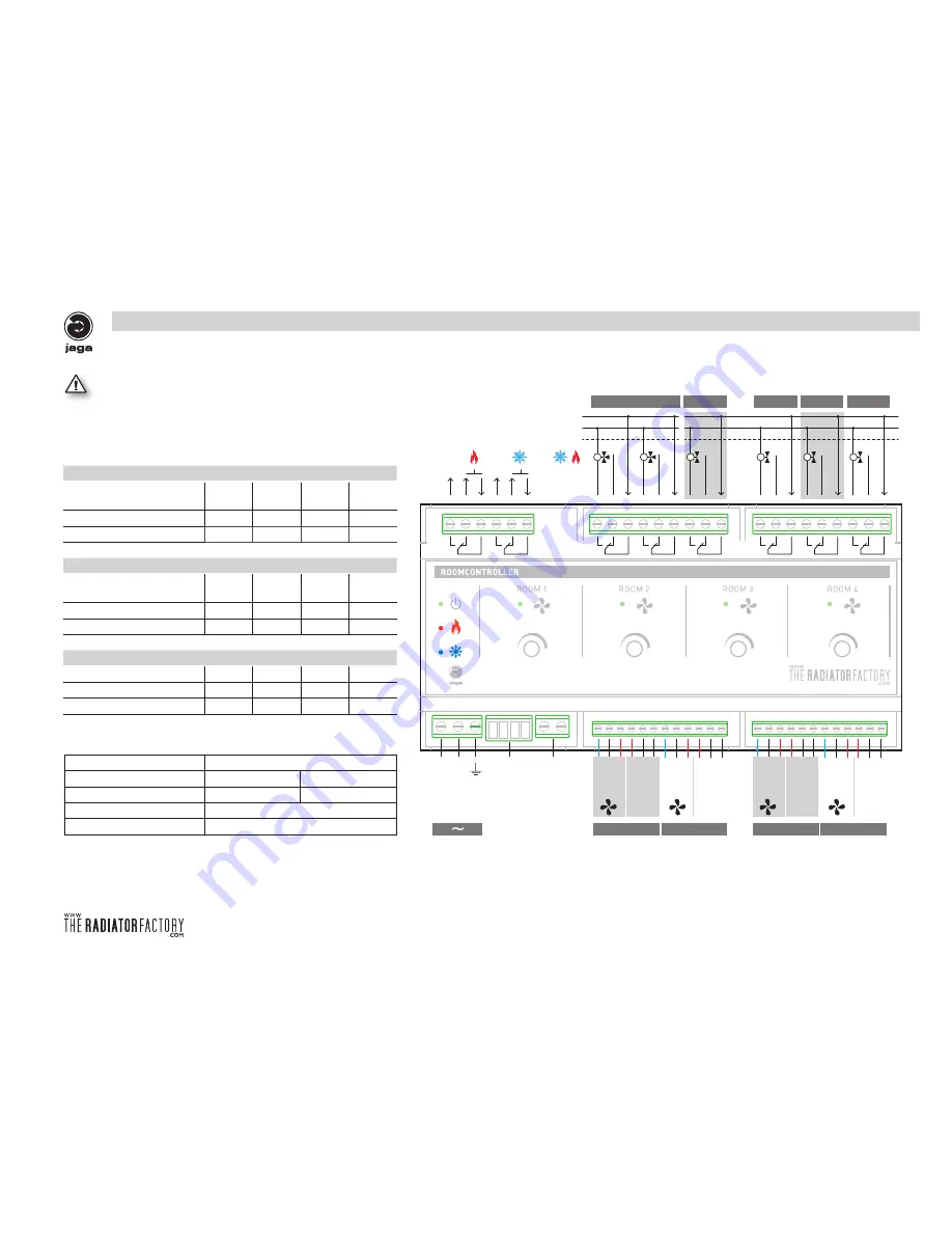
ZONE 1

3-WEG VENTIEL

ZONE 2

ZONE 3

ZONE 4

ZONE 3

ZONE 4

ZONE 1

ZONE 2

 verwarming stanby  

NO: normaal open contact

NC: normaal geslotencontact

N

NO 

N

 koeling stanby  

N

NO 

N

NO 

L1 

PE 

L1 

PE 

NO 

230VAC

230VAC

Externe voeding

Fabric

N

NO 

N

NO 

N

NO 

N

NO 

GND 0..10V +24V +24V

Heating Cooling

GND 0..10V +24V +24V

Heating Cooling

GND 0..10V +24V +24V

Heating Cooling

GND 0..10V +24V +24V

Heating Cooling

TH°

TH°

TH°

TH°

250 VAC / 5A

250 VAC / 3A

250VAC/125VDC

5VDC  100mA

072

108

144

180

12

8

5

4

4.37

6.70

10.30

12.10

052
072

072
092

105
125

125
145

3

3

2

2

17

18

24

26

80

110

160

180

5

4

2

2

3.5

5

8.5

10

Connections

1 Alternating contact

Ohm: AC1 (25°C)

Inductive: AC3 (25°C) 

Nominal charge
Maximum switch off tension
Min. Minimum admissible charge

heating s

tandby

NO: normal open contact

NC: normal closed contact

cooling s

tandby

Ext

ernal P

ow

er Suppl

y

3-WAY VALVE

Maximum numbers of Clima Canals per controller:

Clima Canal
Clima Canal Hybrid:
Number of motors
Consumption (W) per unit (max)

Maximum numbers Briza's per controller:

Built-In:

With casing:
Number of motors
Consumption (W) per unit (max)

Maximum numbers Quatro Canals per controller:

Quatro Canal
Number of motors
Consumption (W) per unit (max)

Maximum number of devices per controller::

  Attention:

A 24V 50W (suitable for driving (eg) up to 2 Briza or 10 Clima Canal engines) is built 

into the casing.

To control more devices use an external power supply.

Example:

Summary of Contents for JAGA

Page 1: ...Canal la tension de sor tie du Jaga Roomcontroller doit tre r gl e au minimum 4 volts F r die Inbetriebnahme der Clima Canal Gebl semotor s den Regler auf mindestens 4 Volt einstellen For startup of...

Page 2: ...ion 2 LED indication operation mode 3 Connections 4 Connections with External Power Supply 5 Example scheme 1 SECTOR heating 6 Example scheme 1 SECTOR heating cooling 7 Example scheme 2 SECTORS heatin...

Page 3: ...zone 1 2 3 4 If zone 1 does not demand the next zone with de mand has priority The room thermostats control the overall demand for heating or cooling When heating and cooling is asked at the same time...

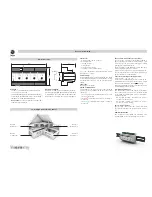
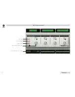
Page 4: ...2 Power On Mode Heating Mode Cooling Manual setting ventilator speed Connection by using screw clamps LED indication operation mode...

Page 5: ...10 Connections 1 Alternating contact Ohm AC1 25 C Inductive AC3 25 C Nominal charge Maximum switch off tension Min Minimum admissible charge heating standby NO normal open contact NC normal closed co...

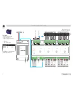
Page 6: ...V Heating Cooling TH TH TH TH GND TOESTELLEN VOEDING 230VAC GND 230VAC 7990 050 31 1 3 7990 051 60 2 5 7990 052 100 4 2 7990 053 240 10 Connections with External Power Supply Power supply DIN rail or...

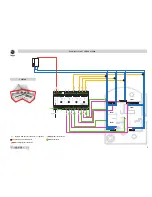
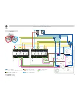
Page 7: ...M T Example scheme 1 SECTOR heating 1 SECTOR Bypass with pressure difference regulator Speed control device Two way valve with motor Thermostat Heating system controller Example scheme 1 SECTOR heati...

Page 8: ...ROOM 1 ROOM 2 ROOM 3 ROOM 4 ROOM 2 ROOM 3 ROOM 4 T M M Example scheme 1 SECTOR heating cooling 1 SECTOR Water Icewater Two way valve with motor Speed control device Bypass with pressure difference re...

Page 9: ...3 ROOM 4 ROOM 3 ROOM 4 ROOM 1 ROOM 1 ROOM 2 ROOM 2 T M M Example scheme 2 SECTORS heating cooling Water Icewater Two way valve with motor Speed control device Bypass with pressure difference regulato...

Page 10: ...8...

Page 11: ...section 2 5 mm2 Cooling 3 Way valve 3 pin connection Max wire section 2 5 mm2 Zone Connection To device Tension device GND Max wire section 1 5 mm2 To device Steering device Protected output0 10V max...

Page 12: ...1012 versie1 Jaga N V...

Reviews: