background image

26- Linkages 

Elevator push rod

Elevator push rod

Tail wheel push rod

Rudder push rod

Throttle push rod

................2

....................3

2mm 

Connector

Elev. servo

Rudder servo

Thrott. servo

BOTTOM VIEW

X

Elevator pushrod
or rudder pusshrod
D=5/64”(2mm)
Tail wheel pushrod
D=.050”(1.2mm)

3mm set Screw

2 mm

Elevator pushrod

ELEVATOR / RUDDER SERVO

X

3mm set Screw

2 mm

THROTTLE SERVO

 throttle pushrod 
 D=.050”(1.2mm)

2.5x10mm

27- Cowling installation 

1~2mm

Board or
transparent
plastic

Adhesive
tape

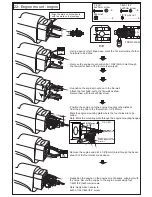
1-Attach the board or transparent plastic on the side of 
the fuselage with the adhesive tape as show.
2-Using a pencil or felt tipped pen trace around the engine 
head where it meet the cowl. Cut the opening the board
or transparent plastic for the engine head as marked before.
3-Remove the engine and insert the cowl on to the fuselage 
so the distance from the fire wall to the front of the cowl is 
4-59/64”(125mm). Trace around inside the hole on the board 
or transparent plastic with a pencil.
4-Remove the cowl from the fuselage and carefully cut the 
opening for the engine head as marked above. Do the same 
way with the hole for needle-valve.
5-Again. Insert the cowl on to the fuselage and secure it in 
place with five 2.5x10mm self tapping screws.

125mm

Ruler

Cut the opening

Cut the opening

1.5mm

1/16”

1.5mm

1/16”

2.5x10mm self
tapping screw

3/32x25/64” self tapping screw

.................4

1/16”

Summary of Contents for P-51 VooDoo

Page 1: ...4 6 channel WARNING This radio control model is not a toy If modified or flow carelessly it could go out of control and cause serious bodily injury or property damage Before flying your airplane ensur...

Page 2: ...ine 12x6 for 60 4 cycle engine 12x7 for 70 4 cycle engine 13x8 for G 46 HP Motor Silicone tube Extension for aileron servo retract servo 46 50 2 cycle REQUIRED FOR OPERATION Purchase separately Linkag...

Page 3: ...ure that the V of the dihedral brace is positioned correctly 7 Do the same way with the other wing half 8 Carefully slide the wing halves together ensuring that they are accurately aligned Firmly pres...

Page 4: ...t option Plywood buffer included with retract set FRONT VIEW WING TOP X Retract landing gear servo 4 Servo Installation TOP VIEW 3 Retract servo tray TOP VIEW Cut away only the covering Note The head...

Page 5: ...small piece of masking tape works well for this Cut off the excess length each rod Ply gear mount plate x 2 Gear mount x 2 2mm Bottom view Ansicht von unten ELECTRIC RETRACT LANDING GEAR 7 Electric re...

Page 6: ...lat and then remove it Using a sharp hobby knife cut away the covering inside the lines Not to cut into the wood Apply the wing bolt flat in place and secure it with CA glue 11 Wing bolt flat Verstark...

Page 7: ...io trims centered then mount the ailerons servo horn in neutral position The servo horn should be perpendicular to the servo YES NO WING BOTTOM VIEW Hinge Line Control horn Alignment Depending on the...

Page 8: ...r 6x40 plastic bolt Ply wood Plastic mount nut Bottom Wing bolt plat 1 Using the ABS air scoop as a template trace around the outside edge of the ABS air scoop and then remove it 2 Using a sharp hobby...

Page 9: ...r in place Check the alignment of the vertical stabilizer When you are satisfied with the alignment use a pencil to trace around the right and left of the stabilizer where it meets the fuselage 2 Remo...

Page 10: ...el gear in place BOTTOM VIEW H D Securely glue together If coming off during flight you lose control of your air plane 5 5 Bottom view 3 8 in 9 5mm push the elevator and its hinges into the hinge slot...

Page 11: ...he distance from the prop hub to the fire wall is 5 1 8 127mm 125 127mm Engine thrust on balk head is already adjust at factory 1 5 TOP VIEW Mark the engine mounting plate where the four holes are to...

Page 12: ...51mm 2 61 64 75mm FUSELAGE BOTTOM X To muffler Filler tube To engine 3x25mm screw Rubber stopper 1 After confirming the direction Insert this assembly clunk end first into the fuel tank and tighten an...

Page 13: ...pencil or felt tipped pen trace around the engine head where it meet the cowl Cut the opening the board or transparent plastic for the engine head as marked before 3 Remove the engine and insert the...

Page 14: ...st of the backing while at the same time adhering the rest of the sticker Try not to make air bubbles if there are some carefully puncture sticker center of bubble but not model surface with the tip o...

Page 15: ...AILERON STROKE Adjust the travel of the control surfaces to achieve the values stated in the diagrams These value will be suitable for average flight requirements Adjust the values to suit your partic...

Reviews: