background image


 HD6-600 Mobile DVR


Page 19 of 67 

Radio Engineering Industries, Inc. 

640611 – 8/17/22 

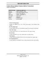
Vehicle Sensor Options Harness Vehicle Connections 

(Shown as School Bus) 


WIRE COLOR 

WIRE DESCRIPTION 

BLACK 

RED WARNING LAMP 

BROWN 

YELLOW WARNING LAMP 

RED 

LEFT TURN SIGNAL 

ORANGE 

RIGHT TURN SIGNAL 

YELLOW 

STOP ARM 

GREEN 

BRAKES 

BLUE 

FRONT DOOR 

VIOLET 

REAR DOOR 


Yellow Warning Lamps


Connect  the  BROWN  wire  to  the  Yellow  lamp  output  of  the  Warning  Lamp 
Flasher.  

Red Warning Lamps 


Connect the BLACK wire to the Red lamp output of the Warning Lamp Flasher. 

Stop Arm Lamps  

Connect the YELLOW wire to the switched side of the stop arm lamp. 

Brake Lamp 

Connect the GREEN wire to the switched side of one brake lamp. 

Turn Signals 

Connect the RED and ORANGE wires to the left and right turn signal lamps. 

Front and Back Doors 

Connect the BLUE and VIOLET wires to the switched side of the door switches. 

Summary of Contents for HD6-600

Page 1: ...HD6 600 Mobile DVR Page 1 of 67 Radio Engineering Industries Inc 640611 8 17 22 Radio Engineering Industries HD6 600 Mobile Digital Video Recorders Hardware User Manual Hardware Installation Manual...

Page 2: ...ule Harness 17 Vehicle Sensor Options Harness 18 Vehicle Sensor Options Harness Vehicle Connections 19 On Screen Information with Vehicle Sensor Options Harness 20 Accelerometer Module Harness 21 Phys...

Page 3: ...D Menu 41 Sub Stream Menu 42 Image Menu 42 Motion Menu 43 OSD Menu 45 Input Setup 45 Speed Menu 46 Inputs Menu 47 Accel Menu 48 GPS Port Menu 49 Network Setup 51 WAN LAN Setup 51 Server 52 WIFI Menu 5...

Page 4: ...12 3 Axis Inertia Sensor Directions 21 Figure 13 L Bracket Mounting 22 Figure 14 DVR Dimensions 23 Figure 15 Security Cover Mounting 23 Figure 16 Connecting to the DVR with a Computer through the Ethe...

Page 5: ...4 Figure 55 Route Setup 54 Figure 56 Firewall Setup 55 Figure 57 Info Menu 56 Figure 58 Camera Tab 56 Figure 59 Inputs Tab 56 Figure 60 Alarms Tab 57 Figure 61 System Tab 57 Figure 62 WAN Cell Tab 58...

Page 6: ...4 analog camera inputs and 2 IP camera inputs This system features a unique compact rugged design engineered to meet the demands of harsh mobile environments The HD6 mobile DVR features the latest te...

Page 7: ...Mbps Compression H 265 Triple stream encoding recording high quality recording efficient network video streaming Audio Inputs 6 Total Channels 6 Storage Hard Drive Removable hard disk or solid state d...

Page 8: ...camera setup etc Front Panel Audio Video Port Front panel composite audio video outputs for local DVR configuration camera setup etc using a USB mouse Vehicle Interface J1939 Dual SAE J1939 250kbps 5...

Page 9: ...HD6 600 Mobile DVR Page 9 of 67 Radio Engineering Industries Inc 640611 8 17 22 System Overview Figure 1 HD6 600 MDVR System Diagram...

Page 10: ...HD6 600 Mobile DVR Page 10 of 67 Radio Engineering Industries Inc 640611 8 17 22 Front and Back Panels Figure 2 Front Panel Layout...

Page 11: ...the mouse returns the display to matrix view Initial Set Up The HD6 600 Mobile DVR system will operate prior to any user setup with the default settings However it may not show the correct time and d...

Page 12: ...it is all the way in Turn the HDD key to the locked and on position Removing HDD Turn the HDD key to the unlocked and off position Grab the handle on the HDD and carefully pull it out Note The HD6 600...

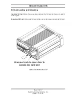
Page 13: ...Inc 640611 8 17 22 SD Card Loading and Unloading Inserting SD Card Open the access door and insert the SD card all the way in until it locks in place Removing SD Card Push on the SD card all the way i...

Page 14: ...HD6 600 Mobile DVR system draws a small amount of current in stand by mode If the systems are installed but not used for an extended length of time i e longer than two weeks it is recommended that the...

Page 15: ...ngineering Industries Inc 640611 8 17 22 Installation Figure 7 System Wiring Power and Camera Cables WARNING DISCONNECT VEHICLE BATTERY VOLTAGE BEFORE INSTALLING System WIRING WARNING DISCONNECT POWER...

Page 16: ...on The optional external record indicator event mark button harnesses Panic Button are available with two different types of switches OEM and aftermarket The OEM switch is rectangular and fits into a...

Page 17: ...in a black water resistant case and designed to withstand rugged operating conditions Information provided to the DVR system includes longitude latitude speed heading date and time Internal memory bac...

Page 18: ...le to the installer SCHOOL BUS and TRANSIT The default SCHOOL BUS monitored points in the vehicle are Red warning lamp operation Amber warning lamp operation Left turn signal Right turn signal Stop ar...

Page 19: ...DOOR Yellow Warning Lamps Connect the BROWN wire to the Yellow lamp output of the Warning Lamp Flasher Red Warning Lamps Connect the BLACK wire to the Red lamp output of the Warning Lamp Flasher Stop...

Page 20: ...ay information on screen in the Installers Mode when the monitored switches on the vehicle are activated and signals are applied to the monitored sensors ACTIVE SWITCH OR SIGNAL ON SCREEN DISPLAY BRAK...

Page 21: ...the DVR hard mounting the accelerometer will prevent the accelerometer readings from being compromised To properly install the Accelerometer Module the user must align the device with the picture on...

Page 22: ...unting Requirements L Bracket Mounting The DVR has two L brackets along the side of the unit to allow easy mounting This type of installation is recommended for vehicles that have a secured compartmen...

Page 23: ...17 22 Figure 14 DVR Dimensions Security Cover Mounting There may be installations that require the front and back of the DVR to be enclosed in a protective enclosure Security covers can be installed...

Page 24: ...ior placement System Start Up To start the recording process start the vehicle Upon turning the system switch ON the HD6 600 Mobile DVR will commence recording System Shut Down To stop the recording p...

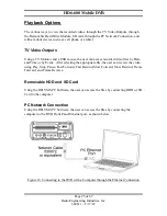
Page 25: ...rded video files by Date and Time or by Event After selecting the appropriate file the user can review the video using Play Stop Pause Fast Forward Fast Rewind Slow Forward Slow Rewind Frame Forward a...

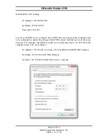
Page 26: ...he TCP IP network settings on the computer need to be configured to match the settings in the DVR to insure both devices are in the same network For example when DVR network is set to default as above...

Page 27: ...REI Toolkit Dongle and the DVR To download the REI DVR Toolkit complete the following instructions If using an Android device From the Google Play Store search for the REI DVR Toolkit by typing REI D...

Page 28: ...gs icon and then select the Wi Fi icon to open the list of available Wi Fi networks under CHOOSE A NETWORK At this point the connection for the example DVR REI 009 should appear on the list of Wi Fi n...

Page 29: ...he name of the DVR REI 009 for example and a Login prompt will appear as shown below Figure 18 Login Window By default the initial password is 10231981 The Remember box could already be checked If not...

Page 30: ...nt from the SD card to the DVR The card operates like a flash drive and the system upgrade content from the SD card will be displayed on the hand held device and the system upgrade steps can be perfor...

Page 31: ...n Menu can be accessed by using any standard USB mouse and video monitor For more convenient usage REI offers its hand held USB trackball mouse P N 690816 The user can access recorded videos and custo...

Page 32: ...five subcategories ID Time Date Start Up Faults and Password The user can give the vehicle a name set the time and date set when the DVR starts recording set fault indicators fault beepers external re...

Page 33: ...is selected except None press the Sync Now button to synchronize the time immediately or the DVR will synchronize time automatically at midnight Time Zone Used with the GPS and Sync Time as GPS satel...

Page 34: ...ng as the ignition signal stays on Schedule DVR starts recording only by schedule regardless of ignition signal Either Ignition or Schedule DVR starts recording by schedule or when ignition is on at t...

Page 35: ...player Faults Menu Figure 28 Faults The Audio Visual Setup menu enables the DVR to display an Audio Visual alert if the DVR is experiencing an alert condition Fault Indicator The types of alerts faul...

Page 36: ...VR to display faults Display Alarms Allows DVR to display alarms Standby Mode Display Display alarms or faults when the DVR is in standby mode Display Faults Allows DVR to display faults in standby mo...

Page 37: ...Sub Stream Image Motion and OSD Under Video the channels can be enabled or disabled and the camera configuration can be set up It is possible to setup the amount of time to record before and after al...

Page 38: ...such as number of cameras resolution frame rate etc Channel Enable Custom camera record setting for each camera Enable All Enable all channels Enable Connected Enable channels with currently connecte...

Page 39: ...een 1 and 30 can be selected Video Loss User can select one of three options Ignore Warn and Alarm Blind User can choose between three options Ignore Warn and Alarm IPC Setup Click to open an IP setup...

Page 40: ...e channel being setup Port Port identification for the channel User name Used to enter camera configuration menu Password Used to enter camera configuration menu Audio Audio codec currently used Click...

Page 41: ...1800 seconds SD Menu Figure 36 SD Setup SD Record Mode Select Alarm or Mirror Alarm Records only alarm video to the SD card Mirror Records video to the SD card continuously SD Record Stream Select Mai...

Page 42: ...Frame Rate The frame rate of the sub stream Ranges between 1 and 30 Quality The quality bit rate of the sub stream Ranges between 10 and 100 of target bit rate 3rd Stream Source Stream to use as the...

Page 43: ...ment for the video from 0 63 Color Color adjustment for the video from 0 63 Saturation Saturation adjustment for the video from 0 63 Mirror Flip A drop down that allows the mirror flip the image of th...

Page 44: ...ion Detect Enable motion detection for the selected channel Motion Alarm Trigger alarm upon motion detection for the selected channel Sensitivity Motion detection sensitivity within each square Ranges...

Page 45: ...ive Record Selected data types will be recorded permanently over video Playback Selected data types will be displayed during playback via monitor mouse Live Selected data types will be displayed durin...

Page 46: ...39 1 and J1939 2 Speed Units MPH and KMH speed units Overspeed Alarm Triggers an alarm if the speed exceeds the Overspeed Threshold for the Overspeed Duration Overspeed Threshold Minimum speed that tr...

Page 47: ...vehicle types to choose from School Bus and Transit When set to custom each channel can have its own name and OSD abbreviation ALPR 1 0 Pod Mode should only be set if you are replacing your REI HD Ser...

Page 48: ...options to configure the accelerometer Calibrate Accelerometer Accelerometer must be calibrated after installation Click the Calibrate button to calibrate the accelerometer Current Values Current acc...

Page 49: ...HD6 600 Mobile DVR Page 49 of 67 Radio Engineering Industries Inc 640611 8 17 22 Figure 47 Accel Alarm Figure 48 Accelerometer Threshold GPS Port Menu Figure 49 GPS Port...

Page 50: ...50 of 67 Radio Engineering Industries Inc 640611 8 17 22 Mode Set the mode of the GPS port Status Out or External GPS input Baud Rate Baud Rate of the GPS Port 4800 115200 The default setting for the...

Page 51: ...igure the DVR to connect to the network It has inputs for WAN LAN settings server WIFI Cellular connections and Routes WAN LAN Setup Figure 51 General Network Setup WAN LAN setup is where the user set...

Page 52: ...Contact your IT specialists for assistance configuring this page Server Figure 52 Server Provisioning Server Provisioning server IP address Provisioning Username Username used to access the Provision...

Page 53: ...IP Mode Static or Dynamic DHCP IP address IP Address WIFI IP Address Netmask WIFI Netmask Security Security type used by WIFI network It must match access point setting Key Security key used by WIFI...

Page 54: ...ineering Industries Inc 640611 8 17 22 Cellular Figure 54 Cellular Setup Configuration for internal cellular card Applicable to cellular models only Contact your IT specialists for assistance configur...

Page 55: ...or assistance configuring this page Firewall Figure 56 Firewall Setup Enable Firewall Select this check box to utilize firewall protection for selected IP URL addresses Enable Select this check box to...

Page 56: ...logs Displayed data is displayed across eight subsections Camera Inputs Alarms System WAN Cell WIFI Versions and Logs Camera Figure 58 Camera Tab Active Channels Channels which have cameras currently...

Page 57: ...Pod Alarms Figure 60 Alarms Tab Active Alarms Alarms that are currently occurring System Figure 61 System Tab Active Faults Faults that are actively occurred System Temp Current system temperature HDD...

Page 58: ...ateway etc of the WAN interface Cell Current IP address Gateway etc of the internal cellular interface Signal Strength RSSI Current signal strength of the internal cellular interface WIFI Figure 63 WI...

Page 59: ...dio Engineering Industries Inc 640611 8 17 22 Versions Figure 64 Versions Tab Version of the Main MCU Firmware Serial Number System ID Model MCU and ALPR version Logs Access to the system or fault log...

Page 60: ...HD6 600 Mobile DVR Page 60 of 67 Radio Engineering Industries Inc 640611 8 17 22 Figure 66 Logs Search Result System Logs Advanced For internal use only Figure 67 Advanced Tab...

Page 61: ...he identification of the user currently in the queue Last Comm The most recent communication between the DVR and the server Maintenance Maintenance allows upgrades to the firmware import or export the...

Page 62: ...en by this function Click Reset To Defaults to reset ALL configuration settings to the factory default Note This will change all network settings including WIFI back to factory defaults Reboot DVR Cli...

Page 63: ...me view of the camera The bar at the bottom of the screen has controls to select which channels are displayed if info window is displayed and to return to the Setup menu Internet Explorer allows for a...

Page 64: ...hannel Selection Figure 76 Channel Selection Buttons Select individual channels for Live View Play Back Figure 77 Playback Menu Playback Videos recorded on the HDD can be fully accessed from the Play...

Page 65: ...the video storage device HDD or SD month and year of the desired video The calendar will display all days in the selected year and month which contain video If the day is green Main stream and Sub str...

Page 66: ...the ability to search alarms from a list The screen shows a list of available alarms Select the video storage device HDD or SD month and year of the desired alarm Select the desired alarm from the lis...

Page 67: ...ons However there is no guarantee that interference will not occur in a particular installation If this equipment does cause harmful interference to radio or television reception which can be determin...

Reviews: