background image

7

Connecting an Antenna

Once you choose an antenna, follow the
mounting instructions supplied with the
antenna. Route the antenna cable to the
CB, then screw the cable into the 

AN-

TENNA

 jack on the back of the CB.

Cautions:

• Do not run the cable over sharp

edges or moving parts that might
damage it.

• Do not run the cable next to power

cables or other CB antenna cables.

• Do not run the cable through a vehi-

cle’s engine compartment or other
areas that produce extreme heat.

USING VEHICLE BATTERY 
POWER

You can power this CB from your vehi-
cle’s battery or from standard AC power
with an optional DC power supply. For
information on using AC power, see “Us-
ing the CB as a Base Station.”

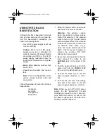
Follow these steps to power the CB from
your vehicle’s battery.

1. Plug the single connector end of the

power cord into the 

POWER 13.8V

DC 

jack on the CB’s back panel.

2. Connect the black wire to your vehi-

cle battery’s negative (–) terminal or
to a metal part of the vehicle’s frame
that is not insulated from the frame
by a plastic part.

3. Connect the red wire, with in-line

fuse, to a source of voltage that
turns on and off with the ignition
switch, such as a spare accessory
terminal in your vehicle’s fuse box.
This prevents the battery from being
drained if you leave the CB on when
you turn off the ignition. 

4. Connect the orange wire, with in-line

fuse, to a source of voltage that sup-
plies constant positive (+) power, or
directly to your vehicle’s positive (+)
battery terminal. This enables the
radio to “remember” the last channel
you tuned to when you turn the radio
back on. 

Illustration

Illustration
Red Wire
Orange Wire
Black Wire

21-1573.fm  Page 7  Thursday, August 5, 1999  9:22 AM

Summary of Contents for 21-1573

Page 1: ...Cat No 21 1573 OWNER S MANUAL Please read before using this equipment TRC 445 Deluxe 40 Channel Mobile CB Radio with Weather Alert 21 1573 fm Page 1 Thursday August 5 1999 9 22 AM...

Page 2: ...rference Hysteresis Squelch Circuit com pensates for fading signals and elimi nates signal chopping during reception Rotary Tuning Control provides maximum convenience when selecting channels LED Chan...

Page 3: ...this CB However the FCC does require that you read and know Part 95 of FCC Rules These rules apply to the operation of a Class D CB We have provided a copy of these regu lations with your CB Warning D...

Page 4: ...9 Adjusting the Standing Wave Ratio 10 Standing Wave Ratio Chart 11 Operation 12 Turning On the CB and Receiving Transmissions 12 Transmitting 13 Listening to Weather Broadcasts 14 Weather Alert 15 U...

Page 5: ...Cautions If you use the TRC 445 in a vehicle mount it securely to avoid damage to the CB or vehicle or injury to any one in the vehicle during sudden starts or stops Do not mount the CB where it could...

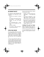
Page 6: ...crophone cable INSTALLING AN ANTENNA Caution To prevent damage to your CB you must connect an antenna to it before you operate it Selecting an Antenna When deciding on an antenna and its lo cation con...

Page 7: ...icle s battery 1 Plug the single connector end of the power cord into the POWER 13 8V DC jack on the CB s back panel 2 Connect the black wire to your vehi cle battery s negative terminal or to a metal...

Page 8: ...e station CB antenna If the antenna starts to fall let it go It could contact overhead power lines If the antenna touches the power line contact with the antenna mast cable or guy wires can cause elec...

Page 9: ...handling 3 10 watts of power such as Cat No 21 549 Simply plug the speaker ca ble s 1 8 inch plug into the CB s EXT SP jack Public Address Speaker To connect a PA speaker to the CB use an 8 ohm speake...

Page 10: ...microphone s talk but ton 5 Set S RF SWR CAL to SWR 6 Press the microphone s talk button again and read the meter s needle on the top SWR scale for the antenna s actual SWR measure ment Refer to the...

Page 11: ...th or anytime the SWR reading is greater than 3 check the condition of the antenna and its coaxial cable RF electrical connections and so on Standing Wave Ratio Chart Ratios Rating Description 1 1 to...

Page 12: ...l it clicks and continue turning until you hear a hissing sound The TX RX indicator lights the CB displays the last tuned channel number and the SWR RF signal meter lights Note If necessary set DIM BR...

Page 13: ...azardous road condi tions and so on Always give emergency communications pri ority on Channels 9 and 19 7 If necessary turn RF GAIN clockwise to boost the strength of a signal 8 If you hear low level...

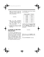
Page 14: ...n FCC for use by the National Oceanographic and Atmo spheric Administration NOAA NOAA broadcasts your local forecast and re gional weather information on one or more of these channels in your area You...

Page 15: ...If the TRC 445 is turned off it does not sound the signal tone USING THE PUBLIC ADDRESS FUNCTION 1 Connect a PA speaker to the TRC 445 see Connecting Optional External Speakers on Page 9 2 Turn OFF V...

Page 16: ...d up in traffic or that you will stop by the store on the way home If you are a two car or more family CBs are great for communicating with family members while they are in their cars Contact friends...

Page 17: ...busy 10 7 Out of service 10 8 In service 10 9 Repeat last message 10 10 Negative NO 10 11 _____ in service 10 12 Stand by 10 13 Report road weather condi tions 10 14 Information 10 15 Message delivere...

Page 18: ...by turning off the engine and oper ating the CB with the ignition set to ACC If most or all of the noise goes away the problem is in your vehicle s ignition or electrical system Here are a few hints t...

Page 19: ...e is securely connected to both the antenna and the CB Trouble with transmission The CB is turned on OFF VOLUME is turned up The microphone is securely connected to the CB All connectors are clean and...

Page 20: ...s and distort or melt plastic parts Keep the CB away from dust and dirt which can cause premature wear of parts Handle the CB gently and carefully Dropping it can damage circuit boards and cases and c...

Page 21: ...Cat No 270 1005 Follow these steps to replace each fuse 1 Make sure the power source and CB are both off 2 To open the fuse holder push the fuse holder ends together then turn either end counterclock...

Page 22: ...put 4 5 Watts Maximum Frequency Response 450 2500 Hz Intermediate Frequency 1st IF 10 695 MHz 2nd IF 455 KHz Cross Modulation 50 dB Squelch Adjustable from 0 5 V to 1 mV TRANSMITTER Output Power 4 Wat...

Page 23: ...s WEATHER RADIO Frequency Coverage 162 400 MHz 162 425MHz 162 450MHz 162 475MHz 162 500MHz 162 525MHz 162 550 MHz Specifications are typical individual units might vary Specifications are subject to c...

Page 24: ...he warranty period take the product and the RadioShack sales receipt as proof of purchase date to any RadioShack store RadioShack will at its option un less otherwise provided by law a correct the def...

Reviews: