
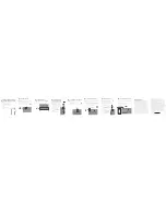
11
12
13
14
15
16
17
18
19
20
Limited Warranty
RadioShack warrants this product against defects in materials
and workmanship under normal use by the original purchaser for
ninety (90) days
after the date of purchase from a RadioShack-
owned store or an authorized RadioShack franchisee or dealer.
RADIOSHACK MAKES NO OTHER EXPRESS WARRANTIES.
This warranty does not cover: (a) damage or failure caused by
or attributable to abuse, misuse, failure to follow instructions,
improper installation or maintenance, alteration, accident, Acts of
God (such as floods or lightning), or excess voltage or current; (b)
improper or incorrectly performed repairs by persons who are not
a RadioShack Authorized Service Facility; (c) consumables such as
fuses or batteries; (d) ordinary wear and tear or cosmetic damage;
(e) transportation, shipping or insurance costs; (f) costs of product
removal, installation, set-up service, adjustment or reinstallation;
and (g) claims by persons other than the original purchaser.
Should a problem occur that is covered by this warranty, take the
product and the RadioShack sales receipt as proof of purchase
date to any RadioShack store in the U.S. RadioShack will, at its
option, unless otherwise provided by law: (a) repair the product
without charge for parts and labor; (b) replace the product with the
same or a comparable product; or (c) refund the purchase price.
All replaced parts and products, and products on which a refund is
made, become the property of RadioShack. New or reconditioned
parts and products may be used in the performance of warranty
service. Repaired or replaced parts and products are warranted for
the remainder of the original warranty period. You will be charged
for repair or replacement of the product made after the expiration
of the warranty period.
4
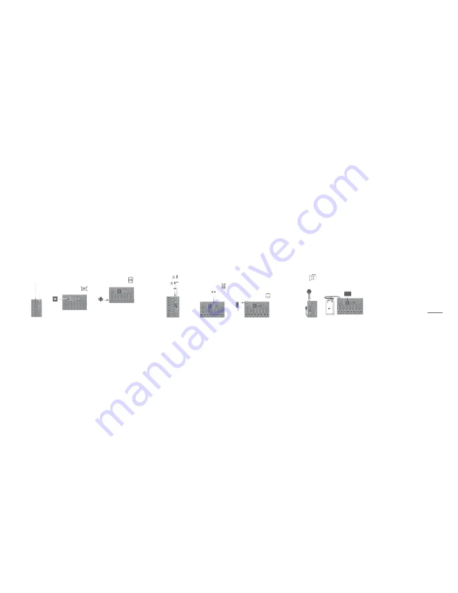
Install the LED and
Electrolytic Capacitor
Note:
The LED and electrolytic capacitor
are polarized and MUST match the position
printed on the PCB. The longer pin is
positive and the shorter pin is negative.
1.
Insert the electrolytic capacitor’s
positive (longer) pin into
C3
+
and
the negative (shorter) pin into
C3
–
.
2.
Solder and trim the excess
leads.
3.
Insert the LED’s positive
(longer) pin into
LED
+
and the
negative (shorter) pin into
LED
–
.
4.
Solder and trim the excess
leads.
5
Install the Ceramic Capacitors
Note
:
Ceramic capacitors are not polarized and can be
inserted facing either direction.
1.
Insert the two ceramic capacitors into
the
C1
and
C2
positions on the PCB.
2.
Solder and trim the excess leads.
6
Install the Battery Holder
Note
:
The battery holder is polarized and MUST match the
position printed on the PCB. The red wire is positive and the
black wire is negative.
1.
To eliminate extra wire, cut the wire with the diagonal
cutters and use your wire strippers to expose a small
amount of wire on the battery buckle.
2.
Insert the red wire into
B
.
3.
Solder and trim the excess wire.
4.
Insert the black wire into
BATTERY –
.
5.
Solder and trim the excess wire.
7
Install the Speaker
Note
:
The speaker input wires are polarized
and MUST match the position printed on the
speaker and PCB. The red wire is positive and
the black wire is negative.
1.
To eliminate extra wire, cut the wire with the
diagonal cutters and use your
wire strippers to expose a small
amount of wire on the speaker.
2.
Connect the red wire into the
+
hole on the back of the speaker
and the
S
hole on the
PCB.
3.
Solder and trim the excess wire.
4.
Connect the black wire into
the
–
hole on the back of the
speaker and the
SPEAKER –
hole on the PCB.
5.
Solder and trim the excess wire.
8
Play Your Electronic Piano
1.
Insert the NE555P IC into the IC socket. The dot on
the NE555P IC should be close to the first pin of the
IC socket.
2.
Install a 9V battery into the battery buckle. The LED
lights.
3.
Press the switches to play tones.
RADIOSHACK EXPRESSLY DISCLAIMS ALL WARRANTIES AND
CONDITIONS NOT STATED IN THIS LIMITED WARRANTY.
ANY IMPLIED WARRANTIES THAT MAY BE IMPOSED BY LAW,
INCLUDING THE IMPLIED WARRANTY OF MERCHANTABILITY
AND, IF APPLICABLE, THE IMPLIED WARRANTY OF FITNESS FOR
A PARTICULAR PURPOSE, SHALL EXPIRE ON THE EXPIRATION
OF THE STATED WARRANTY PERIOD.
EXCEPT AS DESCRIBED ABOVE, RADIOSHACK SHALL HAVE NO
LIABILITY OR RESPONSIBILITY TO THE PURCHASER OF THE
PRODUCT OR ANY OTHER PERSON OR ENTITY WITH RESPECT
TO ANY LIABILITY, LOSS OR DAMAGE CAUSED DIRECTLY OR
INDIRECTLY BY USE OR PERFORMANCE OF THE PRODUCT OR
ARISING OUT OF ANY BREACH OF THIS WARRANTY, INCLUDING,
BUT NOT LIMITED TO, ANY DAMAGES RESULTING FROM INCON
-
VENIENCE AND ANY LOSS OF TIME, DATA, PROPERTY, REVENUE,
OR PROFIT AND ANY INDIRECT, SPECIAL, INCIDENTAL, OR
CONSEQUENTIAL DAMAGES, EVEN IF RADIOSHACK HAS BEEN
ADVISED OF THE POSSIBILITY OF SUCH DAMAGES.
Some states do not allow limitations on how long an implied
warranty lasts or the exclusion or limitation of incidental or conse-
quential damages, so the above limitations or exclusions may not
apply to you. This warranty gives you specific legal rights, and you
may also have other rights which vary from state to state. You may
contact RadioShack at: RadioShack Customer Relations
300 RadioShack Circle, Fort Worth, TX 76102
04/08
www.RadioShack.com
Printed
in Taiwan
01A14
6400254
©2014 RadioShack Corporation. All rights
reserved. RadioShack is a registered
trademark used by RadioShack Corporation.
3
Install Tact Switches
1.
Insert the eight tact switches into the
Do
,
Re
,
Mi
,
Fa
,
So
,
La
,
Ti
,
Do
positions on the
PCB.
2.
Solder the switches in place.
2
Install the IC Socket
Note
:
The integrated circuit (IC) socket MUST match the
position printed on the PCB. The dot on the NE555P IC
should be close to the first pin of the IC socket.
1.
Insert the IC socket into the NE555P IC pin holes on
the PCB.
2.
Solder and trim the excess leads.
Assemble the Electronic Piano Kit
1
Install the Resisters (R1 to R10)
Note:
Resistors are not polarized and can
be inserted facing either direction.
1.
Match and install the 10 resisters
(R1 to R10) to the resistor holes
(also labeled R1 to R10) on the
PCB.
2.
Bend the leads close to the
resistor.
3.
Solder and trim the excess leads.


