background image

— 6 —

DC Voltmeter

Set

PTT

MIC

JACK

ANT

J501

J751

Dummy Load

(50-ohm)

And Attenuator

ALIGNMENT AND ADJUSTMENT

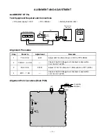
ALIGNMENT OF PLL

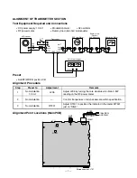
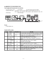
Test Equipment Required and Connections

 DC power supply: 13.8 V

 DC voltmeter

 Dummy load (50-ohm)

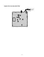
Alignment Point Locations (Main PCB)

Alignment  Procedure

Step

Preset to

Adjustment

Remarks

1

TX 40 CH

L301

Adjust L301 to obtain 3.8 ±0.1 V (DC) at TP3 (R304).

2

TX/RX 1 ~ 40 CH

Check if the DC Voltage on all channels is kept within

1.5 V to 3.9 V at TP3.

3

RX 40 CH

CT301

Adjust CT 301 to obtain 16.71 MHz ±50 Hz at TP7 (R216).

4

WX 1 ~ 7 CH

Check if the DC Voltage on all channels is kept within

1.0 V to 4.0 V at TP4.

DC CORD

FUSE

ANT

J501

TP7

R216

TP3

R304

L301

TP4

R325

CT301

J502

WA901

GND(BLK)

13.8v(RED)

Summary of Contents for TRC-447

Page 1: ...agram 16 Printed Circuit Boards 17 Exploded View and Disassembly Instructions 20 Mechanical Parts List 23 Electrical Parts List 24 Semiconductor Lead Identification 43 IC Internal Diagrams 44 IC and T...

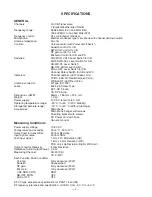
Page 2: ...PA SP 3 5 dia Dimensions HWD 55mm 185 mm 225 mm Weight 1 4 kg Power supply 12 V DC rated 13 8 V DC Operating temperature range 30 C to 50 C FCC Stability Storage temperature range 30 C to 60 C Without...

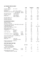
Page 3: ...000 250 4000 Adjacent channel selectivity at 10 kHz dB 50 40 Spurious rejection ratio dB 45 30 Image rejection ratio 910 kHz dB 65 55 IF rejection ratio 10 695 MHz dB 60 50 455 kHz dB 90 60 Audio outp...

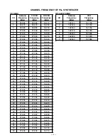
Page 4: ...27 175 16 480 19 27 185 27 185 16 490 20 27 205 27 205 16 510 21 27 215 27 215 16 520 22 27 225 27 225 16 530 23 27 255 27 255 16 560 24 27 235 27 235 16 540 25 27 245 27 245 16 550 26 27 265 27 265 1...

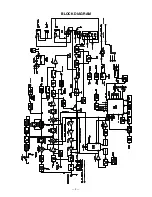
Page 5: ...5 BLOCK DIAGRAM...

Page 6: ...gnment Procedure Step Preset to Adjustment Remarks 1 TX 40 CH L301 Adjust L301 to obtain 3 8 0 1 V DC at TP3 R304 2 TX RX 1 40 CH Check if the DC Voltage on all channels is kept within 1 5 V to 3 9 V...

Page 7: ...ower supply 13 8 V Modulation meter AF oscillator RF power meter Dummy load 50 ohm attenuator Preset ALERT WX CB position CB Alignment Procedure Alignment Point Locations Main PCB Step Preset to Adjus...

Page 8: ...d the AC voltmeter across the dummy load 8 ohm to the external speaker jack J3 Adjust coil L1 L7 to obtain the maximum reading on the AC voltmeter with keeping the level of the SG 2 Vol Standard SQ Mi...

Page 9: ...9 ANT J501 DC JACK J502 GND BLK 13 8v RED L7 L1 L3 J3 L5 L6 L2 L4 L103 RT2 RT1 RT101 DC CORD FUSE Alignment Point Locations Main PCB...

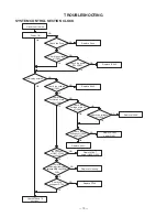
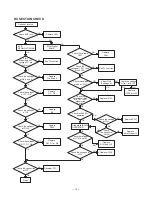
Page 10: ...n 25 of IC401 Check the voltages of IC403 Replace IC403 NG OK Check the voltages of IC402 and Q401 OK Replace IC402 and or Q401 NG Replace X401 the voltages of Q407 Q404 and Q405 OK Replace Q407 and o...

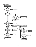
Page 11: ...IC501 AF power IC and or Q10 Change CB WX PA switch to PA Good PA function is good Connect PA speaker and PTT on Input 1kHz signal to MIC Check if Q7 voltages are as shown in voltage chart NG Replace...

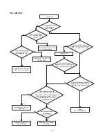
Page 12: ...3 L301 or poor soldering Check whether there is approx 2 3 V at CH1 RX and 3 8 V at CH40 TX at TP3 Check whether each channel frequency matches the frequency indicated in frequency chart Check whether...

Page 13: ...in 16 of IC301 NG Defective xtal X301 or poor soldering OK Check the voltage Q305 NG Defective Q305 Check whether each CH frequency matches the frequency indicated in frequency chart NG Check whether...

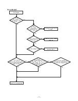
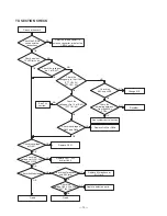
Page 14: ...and 102 Replace IC104 Check the voltages of IC104 Check the voltages of Q1 Q5 Check the connection of TP1 Good Adjust L103 See page 8 Resolder TP1 Replace Q1 Q5 See PLL section NG Replace J501 Check t...

Page 15: ...nt and Main PCBs NG Resolder NG See PLL section OK Check the voltage at Pin 10 of IC301 PTT ON 5V OK Check the voltage at Q402 and Q406 OK NG Replace Q402 or Q406 OK Check the voltage of Q501 NG Repla...

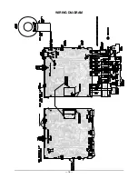
Page 16: ...16 WIRING DIAGRAM...

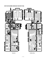
Page 17: ...17 PRINTED CIRCUIT BOARDS Main Top View...

Page 18: ...18 Bottom View...

Page 19: ...19 SWITCH VOLUME LED MIC CH SW SWR PCBs Top View Bottom View...

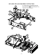
Page 20: ...7 20 6 20 5 20 8 20 2 2 3 20 7 8 17 6 16 15 20 4 7 27 5 EXPLODED VIEW AND DISASSEMBLY INSTRUCTIONS To remove the Top and Bottom Covers Remove eight screws 20 3 from the both sides of Top and Bottom Co...

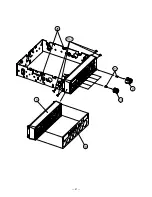
Page 21: ...21 5 13 20 1 21 9 10 26...

Page 22: ...22 12 11 18 23 24 25 19 18 20 3 20 9 20 5 20 10 20 11 20 3 20 12 20 13 20 14 20 12...

Page 23: ...on Plate PVC 30 20 0 5T RZEB407154Z 20 Hardware Kit Base HDWKT367ZHB 20 1 Screw Flat HD M3 4 NI SSCW133004N 20 2 Screw Bind HD M2 6 4 NI SSCW192604N 20 3 Screw Bind HD M3 5 NI SSCW193005N 20 4 Screw B...

Page 24: ...L814725Z C17 Electrolytic 0 47 F 50 V 20 C 156 BCAZ814786Z C18 Ceramic 0 47 F 10 V 10 B BCML114745Z C19 Electrolytic 4 7 F 50 V 20 C 156 BCAZ814796Z C20 Ceramic 0 01 F 50 V 10 B BCML811035Z C21 Cerami...

Page 25: ...ramic 4 pF 50 V 0 25 pF CH BCMM814091Z C103 Ceramic 2 pF 50 V 0 25 pF CH BCMV812098Z C104 Ceramic 0 01 F 50 V 10 B BCML811035Z C105 Ceramic 22 pF 50 V 5 CH BCMM812204Z C106 Ceramic 0 001 F 50 V 10 B B...

Page 26: ...Z C201 Ceramic 0 001 F 50 V 10 B BCML811025Z C202 Not Used C203 Ceramic 180 pF 50 V 5 CH BCMM811814Z C204 Ceramic 270 pF 50 V 5 CH BCMM812714Z C205 Ceramic 27 pF 50 V 5 CH BCMM812704Z C206 Ceramic 180...

Page 27: ...ramic 330 pF 50 V 5 CH BCMM813314Z C307 Ceramic 22 pF 50 V 5 CH BCMM812204Z C308 Ceramic 56 pF 50 V 5 UJ BCMP815604Z C309 Ceramic 0 01 F 50 V 10 B BCML811035Z C310 SemiConductor YR TS2 5S 0 022 F 25 V...

Page 28: ...Electrolytic 100 F 10 V 20 C 156 BCAZ111016Z C416 Electrolytic 1000 F 16 V 20 C 156 BCAZ311026Z C417 Ceramic 0 47 F 10 V 10 B BCML114745Z C418 Ceramic 1 F 6 3 V 10 B BCML901055Z C419 Ceramic 0 022 F 2...

Page 29: ...0492040 D304 405 Not Used D406 1N4003 BDAY0133001 D407 1N4148 T 77 AX TS 26 BDAY0246003 D408 Zener HZ5C1 TD AX TS 26 BDAY0492002 Filter FT1 Ceramic FL 048 SFELA10M7GM00 B0 BFLY0048001 FT2 Ceramic FL 8...

Page 30: ...1 BLDY0087001 L210 Inductor Molded LZ 041 0 47 H K BLZY0041478 L301 LB 1112 M7 D3 31332 BLBY1112001 L302 Inductor Molded LZ 041 1 H K BLZY0041109 L303 Inductor Molded Chip LZ 219 LLQ2012 E47NJ 47N BL...

Page 31: ...1235106 Q410 DB 092 2SA1235A T12 1F BDBA1235106 Q411 DB 092 2SA1235A T12 1F BDBA1235106 Q412 DB 092 2SA1235A T12 1F BDBA1235106 Q413 DB 092 2SA1235A T12 1F BDBA1235106 Q414 DB 092 2SA1235A T12 1F BDBA...

Page 32: ...on Fixed Chip 2 2 ohm 1 16 W 5 BRFC162294Z R46 Carbon Fixed Chip 33 kohm 1 16 W 5 BRFC163334Z R47 Carbon Fixed Chip 47 ohm 1 16 W 5 BRFC164704Z R48 Carbon Fixed Chip 2 2 Mohm 1 16 W 5 BRFC162254Z R49...

Page 33: ...ip 0 ohm 1 16 W 5 BRFC160004Z R119 Carbon Fixed Chip 10 kohm 1 16 W 5 BRFC161034Z R120 Not Used R121 Carbon Fixed Chip 1 5 kohm 1 16 W 5 BRFC161524Z R122 Carbon Fixed Chip 470 kohm 1 16 W 5 BRFC164744...

Page 34: ...n Fixed Chip 1 5 kohm 1 16 W 5 BRFC161524Z R225 Carbon Fixed Chip 22 kohm 1 16 W 5 BRFC162234Z R226 Carbon Fixed Chip 47 kohm 1 16 W 5 BRFC164734Z R227 Carbon Fixed Chip 3 3 kohm 1 16 W 5 BRFC163324Z...

Page 35: ...ohm 1 16 W 5 BRFC161034Z R402 Carbon Fixed Chip 10 kohm 1 16 W 5 BRFC161034Z R403 Carbon Fixed Chip 1 kohm 1 16 W 5 BRFC161024Z R404 Carbon Fixed Chip 270 ohm 1 16 W 5 BRFC162714Z R405 Carbon Fixed Ch...

Page 36: ...m 1 16 W 5 BRFC161034Z R473 Carbon Fixed Chip 10 kohm 1 16 W 5 BRFC161034Z R474 Carbon Fixed Chip 10 kohm 1 16 W 5 BRFC161034Z R475 Carbon Fixed Chip 10 kohm 1 16 W 5 BRFC161034Z R476 Carbon Fixed Chi...

Page 37: ...5 210 3 BRN CUFA021021Z W4 Wire UL 1430 24 5 210 3 RED CUFB021021Z Miscellaneous B1 PCB Main Not repairable PA 432AA BPAY0432AA1 TP1 Test Pin TP 122 1820 01 PP1 BTPY0122001 Shield Case SPTE T 0 3 HSD...

Page 38: ...3 5 70 3 5 8P BWFY3530700 FC552 WF 349 3 5 70 3 5 2P BWFY3490700 FC553 WF 351 3 5 70 3 5 5P BWFY3510700 Resistors R550 Carbon Fixed Chip 10 kohm 1 16 W 5 BRFC161034Z R552 Carbon Fixed Chip 10 kohm 1...

Page 39: ...B 10 Flat Cable FC601 WF 353 3 5 70 3 5 8P BWFY3530700 FC602 WF 352 3 5 70 3 5 6P BWFY3520700 Resistors R601 Carbon Fixed Chip 22 kohm 1 16 W 5 BRFC162234Z R602 Carbon Fixed Chip 0 ohm 1 16 W 5 BRFC1...

Page 40: ...ors against temperature B 10 C701 Ceramic 0 01 F 50 V 10 B BCML811035Z C702 Ceramic 0 01 F 50 V 10 B BCML811035Z Diodes D701 LED TLR 124 BDAY0100001 D702 LED TLSG 126 BDAY0756001 D703 LED LTD 482GC 08...

Page 41: ...following codes indicate variations of capacitors against temperature B 10 Flat Cable FC751 WF 351 3 5 70 3 5 5P BWFY3510700 Jacks J751 MIC 3JK 1139 BJKY1139001 Resistors R751 Carbon Fixed Chip 4 7 ko...

Page 42: ...01 Bushing YD 019 B312D 11 A BYDY0019003 YI502 Insulation Sheet YD 041 AC223 BYDY0041001 W501 W 004 UL 1571 26 5 40 3 BLK CUPK004021Z W502 W 004 UL 1571 26 5 50 3 RED CUPB005021Z WA901 DC Cord WZ 517...

Page 43: ...A C 2SC2001 2SC941TM O A Anode C Cathode LTD 482GC Cathode Anode B C E 2SC2078E 2SC2314F 2SA812 2SA1235 2SC2714 2SC5065 F1 E1 A1 G1 D1 C1 B1 F2 E2 A2 G2 D2 C2 B2 1 2 3 4 5 6 7 8 9 10 11 12 13 14 15 16...

Page 44: ...SCIN OSCOUT MODE TEST DOUT DT1 DT2 DTQ SO S1 VDD TO CR DTDET STR 1 2 3 4 5 6 7 8 9 10 20 19 18 17 16 15 14 13 12 11 IC401 PD789166 1 2 3 4 5 6 7 8 9 10 11 P60 ANI0 P60 ANI1 P60 ANI2 P60 ANI3 P60 ANI4...

Page 45: ...NT INPUT 1 2 OUTPUT 3 3 GND IC502 L7808CV 1 2 3 4 5 1 Non inverting input 2 Inverting input 3 Ground 4 Output 5 Supply voltage IC501 TDA2003V 5 R10 Q15 4 Q16 3 G5 R9 Z4 D6 G4 Q14 D8 D7 Q13 Q12 Q11 D5...

Page 46: ...5V NOM 1 3V DOWN PTT_CH 2 4 5V CH9 2 5V NOR 0V CH19 CH_MODE 3 5V MON ON 0V MON OFF MON 4 0 3V Alert Pulse Alert SAME 5 2 5 2 5 0 0 1 7 0 0 PA_WX 6 0 0 0 0 0 0 4 9 SC 7 5V DUAL ON 0V DUAL OFF DUAL 8 5...

Page 47: ...5 5 0 5 0 5 0 5 0 VDD 16 5 0 5 0 5 0 5 0 S1 17 5 0 5 0 5 0 5 0 S0 18 NC 19 0 0 0 0 0 0 0 0 DT2 20 0 0 0 0 0 0 0 0 DT1 Symbol No Pin TX WX RX Comment PA Mode Pin 1 1 4 1 4 1 4 1 4 IN 2 0 8 0 8 0 8 0 8...

Page 48: ...0 8 0 Q15 C 7 7 7 7 0 0 0 0 B 7 2 7 2 8 0 8 0 E 0 0 0 0 Q16 C 0 9 0 9 B 0 6 0 6 E 7 6 7 6 Q17 C 0 0 0 0 B 7 6 7 6 Symbol No Pin TX WX RX Comment PA Mode Pin E 0 0 0 0 Q18 C 0 0 0 0 B 0 0 0 0 E 0 0 0...

Page 49: ...se E 0 0 0 0 0 0 0 0 Q406 C 0 1 7 9 7 9 7 9 B 0 7 0 0 0 0 0 0 E 4 1 4 1 4 2 4 1 CB 20CH WX 4CH Q407 C 5 7 5 7 6 2 5 7 B 4 8 4 8 4 8 4 8 E 2 5V Switching Pulse Q408 C 0 2V Switching Pulse B 1 5V Switch...

Page 50: ...51 50 SCHEMATIC DIAGRAMS 21 1576 Main PCB...

Page 51: ...52 SWITCH VOLUME LED MIC CH SW SWR PCBs 21 1576...

Page 52: ...RadioShack Corporation Fort Worth Texas 76102 21 1576 04A04 Printed in Japan...

Reviews: