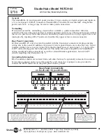
background image

For Assy:

MINITIE12-8

MINITIE6-8

Rev: 01/05

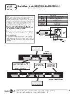
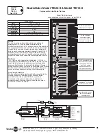
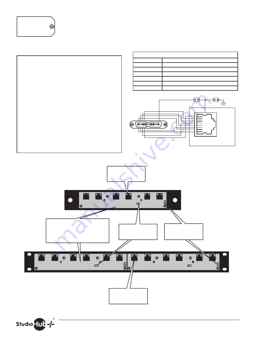
St Model MINITIE6-8 & MINITIE12-8

Engineered for Inter-Studio Tie Lines

General
Mini Tie Hubs provide multi-pair inter-studio connectivity by
splaying out CAT-5 25 pair cable to individual RJ-45
connectors via a 50 pin RJ-21 mass connector. Mini Hubs are
designed to mount and fit where the capacity of full-size hubs
is not needed. Depending on the model selected, either 2 or
4 CAT-5 pairs are connected to each RJ-45 connector.
Double the density is achieved if only 2 pairs (4 wires) are
required to connect to each RJ-45. Generally, 2 pair is
sufficient to support StudioHub analog and digital audio
circuits. All 4 pairs (8 wires) are needed to support KVM and
other special multi-wire equipment circuits.

Mounting
Mini tie-line hubs are available in single units on small wall-
mountable plates, or in double density on 1 r.u. rack mounts

Grounding Information.
RJ-45 connector shields are common on the mini tie hubs.

Two jumpers are provided that allow the unused CAT-5 25

th

pair to be connected to this common shield, as well as to the
hub chassis.

Each RJ-45 provides 8

wires of connectivity via
the CAT-5 25-pair cable

Name

MINITIE6-8 / MINITIE12-8

Mount

Wall Mount / Rack Mount (1 r.u.)

Channels

 6/12

CAT-5 Pairs

8 (all)

Power Link

no

Connectors

RJ-21, RJ-45

Versions

Plate, Rack

Product Key

8

7
6

5

4

3
2

1

Shield

RJ- 45

Hub

Chassis

Ground

JU2

J4

J1

JU1

Unused

Pair

x 12
or 6

RJ-21

Each RJ-45 provides 8

wires of connectivity via
the CAT-5 25-pair cable

RJ-21 connects 25-pair CAT-5 cable

carrying six 4-pair circuits. One 25-pair

CAT-5 cable is required for 6 circuit

model.  Two 25-pair CAT-5 cables are

required for 12 circuit model.

Insert jumper to tie

power supply shield to

hub chassis ground

Insert jumper to tie

power supply shield to

hub chassis ground

Model - MINITIE6-8

Model - MINITIE12-8

Radio Systems, Inc.  

601 Heron Drive 

Logan Twp., New Jersey  08085

(856) 467-8000 

Fax (856) 467-3044 

www.studiohub.com

bl

Summary of Contents for DA12-DC

Page 1: ...Technical Manual for Hubs Updated 09 07 ...

Page 2: ...el GPI Relay Hub rack mount MiniTie12 4 bk 4 wire 12 channel Tie Line Hub mini wall mount MiniTie24 4 bk 4 wire 24 channel Tie Line Hub mini wall mount MiniTie6 8 bl 8 wire 6 channel Tie Line Hub mini wall mount MiniTie12 8 bl 8 wire 12 channel Tie Line Hub mini wall mount Tie12 4DC bm 4 wire 12 channel Tie Line Hub with DC Link Tie24 4DC bm 4 wire 24 channel Tie Line Hub with DC Link Tie12 8 bn 8...

Page 3: ...D 15V 15V Shield Shield Wht Org Org Wht Wht Grn Grn Wht Wht Blu Blu Wht Wht Brn Brn Wht Wht Slt Slt Wht 1 2 3 6 5 4 7 8 Shield Shield 3 4 5 6 1 2 7 8 9 10 Color Pair RJ 45 Pins 110 Pins StudioHub Pinout Chart TR TR R R n c n c n c n c x x Ethernet c c c c c c c c c c c c c c c c c c c c c c c c c c c c c c c c c c c c c cc c c c c c c c c c c c c c c c c c c c c c c c c c c c c c c c c c c c c c c...

Page 4: ...on For Assys HUB16 DC HUB8 DC Rev 01 05 Note All 3 of these jumpers must be inserted for any channel that is powering a remote DC Link device e g StudioHub MatchJack or Pre Amp Name HUB16 HUB8 Mount Hub 3 r u Channels 16 8 CAT 5 Pairs 4 all Power Link yes Connectors 2 RJ 45 110 Versions Full Hub Half Hub Board Only Product Key Insert jumper under any right hand jack to connect that channel s shiel...

Page 5: ...ve any right hand RJ 45 of that channel Name HUB18 DC Mount Hub 3 R U Channels 18 CAT 5 Pairs 2 pins 1 2 3 6 Power Link yes Connectors Mini amp RJ 45 Versions Full Hub Product Key 10 pin 110 style connector provides access to all 4 CAT 5 pairs and cable shield Upper and lower 2 pin mini amp connectors wire to source gear audio I O via certain harness cables Note All 3 of these jumpers must be inse...

Page 6: ...ont panel metalwork A rear panel ground pin exists to allow the interconnection of a ground lead from the harness cable bundle Name HUB32 Mount Rack 1 R U Channels 32 CAT 5 Pairs 2 1 2 3 6 Power Link no Connectors Mini amp RJ 45 Versions Rack Mount Product Key 8 7 6 5 4 3 2 1 Shield RJ 45 x 32 J19 J18 1 2 AES L R J1 1 2 Install Cable to Chassis Ground if Desired J17 J50 Mini Amp Mini Amp SHLD 1B 1...

Page 7: ...common to be in common with the chassis ground If you have a StudioHub 15V power supply connected to the hub to connect each RJ 45 to the power supply shield insert a jumper above each RJ 45 Insert JU 33 to common the chassis ground and power supply shield Name HUB36 Mount Hub 3 R U Channels 36 CAT 5 Pairs 2 pins 1 2 3 6 Power Link yes Connectors Mini amp RJ 45 Versions Full Hub Product Key Insert...

Page 8: ... Pin L AES Wht Org 1 3 L AES Org Wht 2 4 R Wht Grn 3 5 R Grn Wht 6 6 nc Wht Blu 5 1 GND Blu Wht 4 2 15V Wht Brn 7 7 15V Brn Wht 8 8 Shield Wht Slt Shield 9 Shield Slt Wht Shield 10 NOTE These pin outs typically correlate 1 to 1 for Audio Science series 4000 5000 and 6000 audio cards so that straight thru patch cables may be utilized Digital I O Connector MD 26 INPUT 1 LEFT 1 INPUT 1 RIGHT 2 INPUT ...

Page 9: ...Radio Systems Inc 601 Heron Drive Logan Twp New Jersey 08085 856 467 8000 Fax 856 467 3044 www studiohub com 8 ...

Page 10: ...JU3 JU4 JU5 JU6 JU7 JU9 JU10 JU11 JU12 JU13 JU14 JU15 JU16 JU17 JU18 JU19 JU20 JU21 JU22 JU23 JU24 JU8 JU1 JU2 JU3 JU4 JU5 JU6 JU7 JU9 JU10 JU11 JU12 JU13 JU14 JU15 JU16 JU17 JU18 JU19 JU20 JU22 JU23 JU24 JU8 Cross cut between RJ 21 110 connectors and RJ 45 110 connectors to program RJ 21 to RJ 45 control line connectivity JU21 RJ 45 Control Adapters Custom RJ 45 to DB connector adapters are avail...

Page 11: ...ts Grounding Information RJ 45 connector shields are common on the mini tie hubs Two jumpers are provided that allow the unused CAT 5 25 th pair to be connected to this common shield as well as to the hub chassis 8 7 6 5 4 3 2 1 Shield RJ 45 Hub Chassis Ground JU2 J1 JU1 J2 Unused Pair 25 x 24 or 12 RJ 21 Each RJ 45 provides 4 wires of connectivity via the CAT 5 25 pair cable Name MINITIE12 4 MINI...

Page 12: ...ack mounts Grounding Information RJ 45 connector shields are common on the mini tie hubs Two jumpers are provided that allow the unused CAT 5 25 th pair to be connected to this common shield as well as to the hub chassis Each RJ 45 provides 8 wires of connectivity via the CAT 5 25 pair cable Name MINITIE6 8 MINITIE12 8 Mount Wall Mount Rack Mount 1 r u Channels 6 12 CAT 5 Pairs 8 all Power Link no...

Page 13: ... to this common shield bus In addition on powered models the power supply shield may be jumper connected to the RJ 45 shields Name TIE24 4Powered Mount Full Hub Half Hub Channels 24 12 CAT 5 Pairs 2 pins 1 2 3 6 Power Link yes Connectors RJ 21 2 RJ 45 Versions Full Hub Half Hub Board Only Product Key Two RJ 45 s in parallel to bridge inputs and outputs Note All 3 of these jumpers must be inserted ...

Page 14: ...be added The power option is only available on 2 pair per RJ 45 Hub models Grounding Information RJ 45 connector shields may be optionally connected to the chassis ground by inserting a jumper A jumper is also provided to allow the unused CAT 5 25 th pair to be connected to this common shield bus In addition on powered models the power supply shield may be jumper connected to the RJ 45 shields Nam...

Page 15: ...u rack panel via RJ 45 connectors Standard RJ 45 shielded or non shielded straight thru patch cords of 18 or longer may be used to make patch connections Normalling Front panel accessible normalling dip switches establish a quarter normalled full time connection between the upper and lower output and input connectors so that signal in made without the use of a patch cord Note that when the normall...

Page 16: ...D AES EBU MODEL 1 3 rd WIDTH REAR PANEL ADAPTER 2 RJ 45 connectors each conducting 4 pair all RJ 45 pins to 1 pair each RJ 45 pins 1 2 of four front panel RJ 45 s JU8 EDAC MODEL 1 3 rd WIDTH REAR PANEL ADAPTER 16 EDAC 556003520102 male 3 pin connectors with wings removed each conducting 1 balanced audio signal to 1 channel of 1 front panel RJ 45 SHIELD SHIELD SHIELD SHIELD JU4 JU3 JU2 JU1 SHIELD S...

Page 17: ... Note the same applies to jumpers for inputs 2 3 4 above LED s indicate presence of 15V DC Insert jumpers in header to connect hub electrical ground to chassis ground Insert jumper in header to connect output RJ 45 connector shield to Hub electrical ground Install jumper in upper header to add input to output 1 Install jumper in lower header to add input to output 2 Note the same applies to jumper...

Page 18: ...d Green LED s indicate audio presence at 24 dB 15V DC Power connector for pass thru power on dual Hub dual DA or dual Mixer panels LED s indicate presence of 15V DC Insert jumpers in both headers to mono input Insert jumper under output headers to connect RJ 45 shielded to Hub electrical ground Jumper right and center pins on both headers to increase input level sensitivity by 10 dB Jumper left an...

Page 19: ...Radio Systems Inc 601 Heron Drive Logan Twp New Jersey 08085 856 467 8000 Fax 856 467 3044 www studiohub com For Assy Part 14691 rev 01 07 ...

Reviews: