Radio Systems, Inc.
•
601 Heron Drive
•
Logan Twp., New Jersey 08085
(856) 467-8000
•
Fax (856) 467-3044
•
www.studiohub.com
For Assy:
HUB18-DC
Rev: 01/05
St Model HUB18-DC
Engineered for Break-Out Harnesses
General
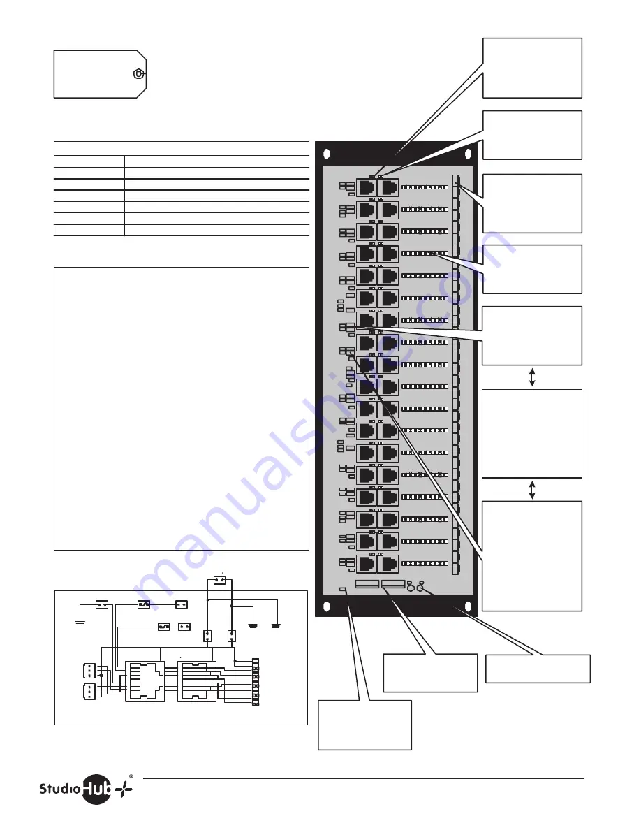
Each of 18 Hub channels consists of two 2-pin mini-Amp
input connector in parallel with an RJ-45 connector and 100-
style punch-down connector. Each channel carries a stereo
balanced audio pair, or balanced digital audio signal. Custom
length and configuration harness cables must be factory
ordered to interconnect the Hub to various consoles, audio
routers and engines or multi-channel Digital Audio
Workstations.
DC Power
If using any St "DC-Link" accessories, plug a
St +/- 15 volt power supply into the power supply
connector. Both Hub LED s will illuminate. Insert both
power jumpers and ground jumper only on only the circuits
that utilize a powered accessory (e.g. MatchJack, mic preamp,
etc.).
Grounding Information
RJ-45 connector shields may be isolated from each other or
optionally connected to each other or to the hub chassis by
inserting jumper by each connector.
To use the hub as a common ground point, insert a jumper
above any left-hand RJ-45 for any channel that you want to be
in common with the chassis ground. If you have a
St 15V power supply connected to the hub, to
connect a channel to the power supply shield, insert a jumper
above any right-hand RJ-45 of that channel.
Name
HUB18-DC
Mount
Hub (3 R.U)
Channels
18
CAT-5 Pairs
2 (pins - 1,2,3&6)
Power Link
yes
Connectors
Mini-amp & RJ-45
Versions
Full Hub
Product Key
10 pin 110-style
connector provides
access to all 4 CAT-5
pairs and cable shield
Upper and lower 2-pin
mini-amp connectors
wire to source gear audio
I/O via certain harness
cables
Note:
All 3 of these
jumpers must be inserted
for any channel that is
powering a remote DC-
Link device (e.g.
St MatchJack
or Pre-Amp)
Install both DC jumpers
to activate St
DC-Link connection to
p/-15V DC to
any powered accessory
This jumper connects the
channel to the common
power ground bus when
installed. Required for
DC-Link operation.
Note: This jumper must
be removed for KVM
extender links and other
data devices that use
CAT-5 wire #4 (blu/wht)
LED s indicate presence of
+/- 15V DC
+/-15V external power
supply main and loop-
thru jumpers
8
7
6
5
4
3
2
1
Shield
RJ- 45
Power
Supply
Shield
JU2
x 18
8
7
6
5
4
3
2
1
RJ- 45
110 Connector
1
2
3
J5
J1
+
-
S
1
2
3
+
-
S
AES/L
R
J2
J3
JU3
15v-
15v+
Power
Supply
Ground
JU5
1/2 Amp
auto reset
fuse
R2
JU4
R1
1/2 Amp
auto reset
fuse
J4
Hub
Chassis
Ground
JU1
JU91
Shield
Blu/Wht G
Wht/Org L+
Org/Wht L-
Wht/Grn R+
Grn/Wht R-
Wht/Brn -
15V
Brn/Wht +
15V
Slt/Wht Shd
Wht/Slt Shd
Wht/Blu n/c
Insert jumper JU91 to
connect the chassis
ground to the power
supply shield
Insert a jumper above
any right-hand RJ-45 to
connect that channel to
the power supply shield
Insert a jumper above
any left-hand RJ-45 to
connect that channel to
the common Hub chassis
ground boss
4


