PG
16
PG
16
PG
17
O
or
B AUX
n
Y
n
R G
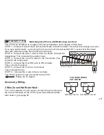
Multi-stage Heat Pump with Multi-stage Aux Heat
The CT80 can handle up to 2 stages of Pump compression and 3 stages of AUX heat.
STEP 1 - Connect O wire to the O terminal
or
B wire to the B terminal. This connects the change-over valve.
If you have both O and B - connect only the O wire to the O terminal and DO NOT connect B to B terminal
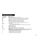
(see wire reference under Trane for B wire terminal).
STEP 2 - Connect the AUX 1, AUX 2, AUX 3 to the W, W2 and W3
respectively. This connects the auxiliary heat.
STEP 3 - Connect the Y and Y2 wires to the Y terminals. This
connects the compressor.
STEP 4 - Connect the R (or RH) wire to RH terminal.
This connects the power.
STEP 5 - Connect the G wire to G terminal.
This connects the fan.
STEP 6 - Connect the C wire to the C terminal.
Your HVAC system is now connected to the CT80.
Please Go To Page 6
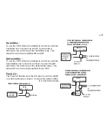
Accessory Wiring -
3 Wire Zoned Hot Water Heat -
For 3 wire solenoid or motor valves connect the wires shown to
the correct terminals on the CT80. If you have different letters
than shown, go to page 20.
R
C and
R
H
connected
HVAC SYSTEM
POWER
B
G
R
Y Y
2
C
O
or
or
AUX1 AUX2 AUX3
THERMOSTAT TERMINALS
C H B O W W2 W3 Y Y2 RH RC G A
DH
EX
SOLENOID VALV
E
W
A
RH
CT80
MOTOR VALVE
W
RH A
CT80
F
O
R 3WIRE Z
O
NED
HOT WATE
R
W
R
A
W
R
A


