6100-Gfast Multifunction Copper Tester Operation Manual
© 2020 Radiodetection Ltd
71
ground potential, and some noise may couple onto
communications circuits.
Depending on where you measure the station ground,
check the bonding lugs on cross-boxes, pedestals, and
electronics/remotes, as well as cable and terminal
bonds. These all need to be good quality and tight. If
you think the ground rod/plane is inadequate, please
consult your support, management, or procedures.
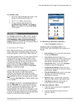
The
Station Ground
parameters are as follows:
Current Group
is the current test group name,
for example
Multimeter
.
Current Test
displays the test being
measured. Here you can switch to another
Multimeter
test from the given list. However,
this action will terminate the ongoing
measurement test.
Threshold Settings
button opens a new page
that allows you to set the
Ground Resistance
Threshold
for the test.
Show hookup diagram on test setup
- If
Yes
,
the
Confirmation
page is prompted before
every
Station Ground
test is started. Select
No
to hide the diagram next time you run the
test.
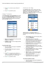
Hookup Diagram
button opens a
Confirmation
page displaying how to connect
your leads at the beginning of the test. The
hookup diagram uses the following graphic and
textual components:
o
Proceed
button closes the hookup
diagram prompt and starts the test.
o
Cancel
button closes the hookup
diagram prompt only.
o
The
Confirmation
window is prompted
before every
Station Ground
test is
started if you selected
Yes
for the
Show hookup diagram
. You can
select
No
to hide the diagram next time
you run the test.
However, you can check the
connection diagram at any time by
pressing the
Hookup Diagram
button.
In this case, the test does not start
when you press the
OK
button to close
the
Confirmation
window.


