15
ADJUSTMENTS
We deliver the antenna with a pre-set mark on each band. Note the
yellow mark on the end of each wire. But this is just a reference based on the
results obtained from the prototypes and so you will need to check it out and
fine tune it to your operating preference. And always remember this basic rule:
to lower the resonant frequency, increase the length of the antenna. To
increase frequency, decrease length.
The development of the first prototypes required a lot of dedication
and time until we could achieve a good efficiency of this antenna. All this work
was rewarded with many QSOs and DX on all bands with the antenna
installed a few meters (feet) from the ground.
Adjusting your Cobweb antenna is a process that requires a lot of
patience and time to get the best performance.
( ) You must have assembled your antenna in a wide place. Make sure
these obstacles that could interfere with performance.
( ) If you have an antenna analyzer, it would be ideal for you to make
trees, walls and fences. Leave at least a 2 meter (6 ft.) distant from
adjustments more easily.If an analyzer is not available, use a trans-
ceiver with power reduced to 5W.
that when raising the antenna it is not too close to obstacles such as
This antenna has limited badwidth with an acceptable SWR. Thus, it is
important that you define which is the preferred segment of operation in each
band and try to leave each band adjusted to your preference. But, you will have
a better result using and antenna tuner.
BASIC RULE TO ADJUST
Higher frequency - Decrease the length
Lower frequency - Increase the length
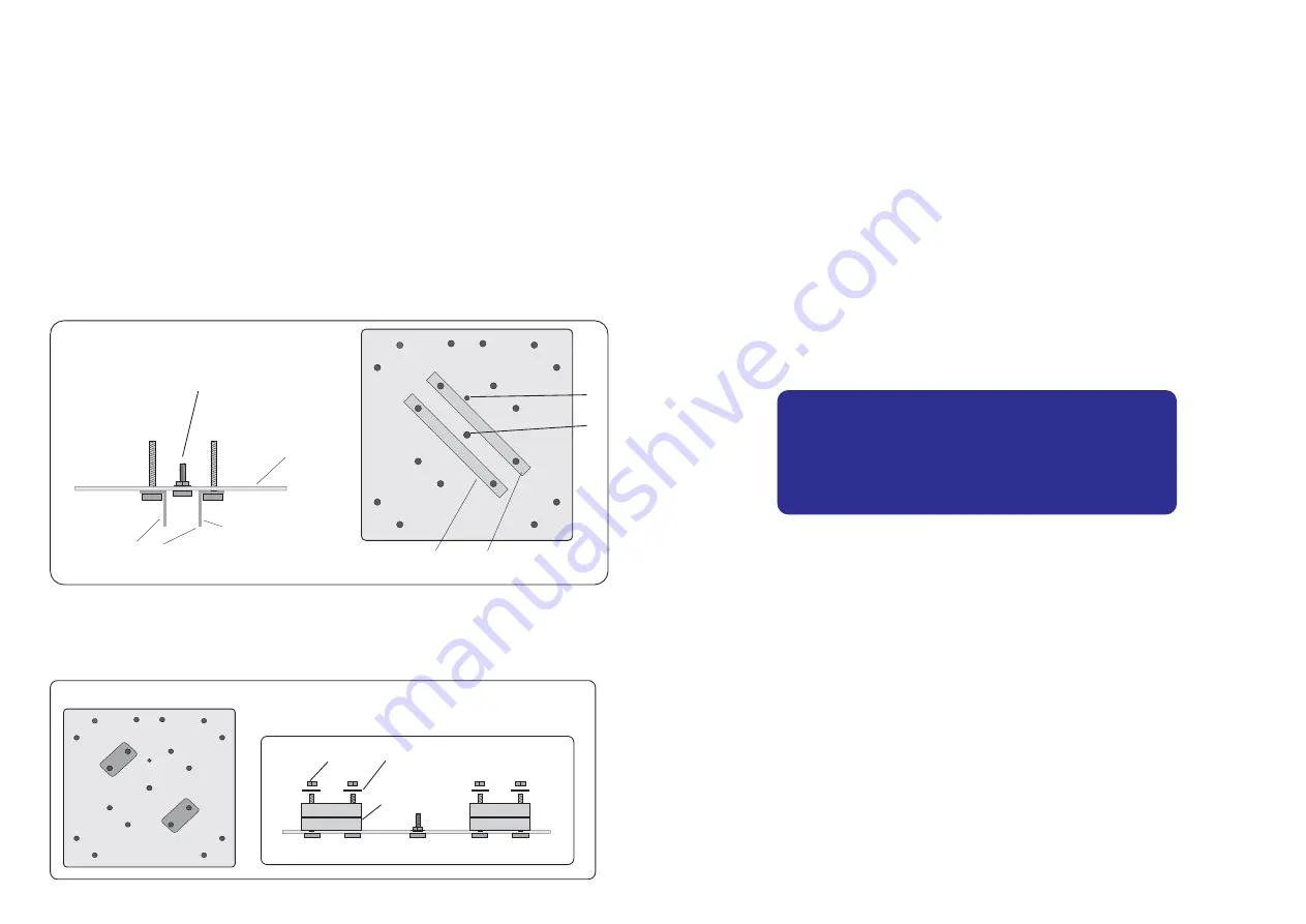
( ) Take the two L-shapped plates (small) and place them on the under
( ) Pass an M6 x 25mm bolt (small) into the center hole (A). Place an
side of the large plate as shown in figure 1.
( ) Pass two M6 x 40mm hex bolt (large) into each L-shapped plate.
( ) Place the large mouting plate on a table or worktop.
ASSEMBLY
M6 flat washer over the bolt and tighten gently with a nut. Over the
ce the point "B". Tighten the nut in this position and remove the
1. Central support bracket assembly
bolt, thread the support mast with ropes and make the white dot fa-
mast.
A
B
Figure 1
L-shaped plates must be assembled
in these position
Bigger size
Central support
(large plate)
Central bolt
(PointA)
( ) On the four threads of these bolts (figure 2), place two 25 mm
so it doesn't fall out
.
(1-inch) plastic tube clamps (large).
( ) Pass flat washers and nuts but do not tighten. Just insert the nut
Tube clamp
(1-inch)
Flat washer
Nut
Figure 2
6
L-shaped plates must be assembled
in these position


