10
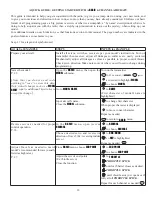
Receiver
Output and
Channel
Helicopter (
HELI
)
1
aileron (cyclic roll)
2
elevator (cyclic pitch)
3
throttle
4
rudder
5
VSDUHJ\UR
6
pitch (collective pitch)
7
VSDUHJRYHUQRU
8
VSDUHPL[WXUHFRQWURO
9
spare
10
spare
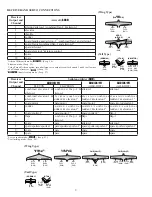
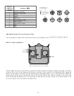
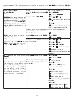
(Swash Type)
HR3
H-1
H-3
ELE
ELE
ELE1
ELE2
120˚
120˚
120˚
PIT
(AIL)
AIL
(PIT)
PIT
(AIL)
AIL
(PIT)
HN3
120˚
120˚
120˚
ELE
PIT
AIL
HE3
ELE
PIT
(AIL)
AIL
(PIT)
PIT
(AIL)
AIL
(PIT)
H-2
PIT
FRONT
AIL
H-4
ELE1
ELE2
AIL
PIT
H4X
(Normal linkage type)
H-1
:each servo linked
t o t h e s w a s h p l a t e
independently.
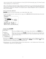
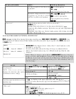
Adjusting the length of the non-slip control sticks
You may change the length of the control sticks to make your transmitter more comfortable to hold and operate.
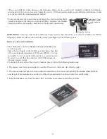
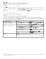
Stick lever tension adjustment
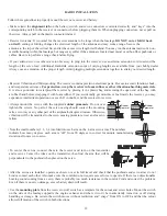
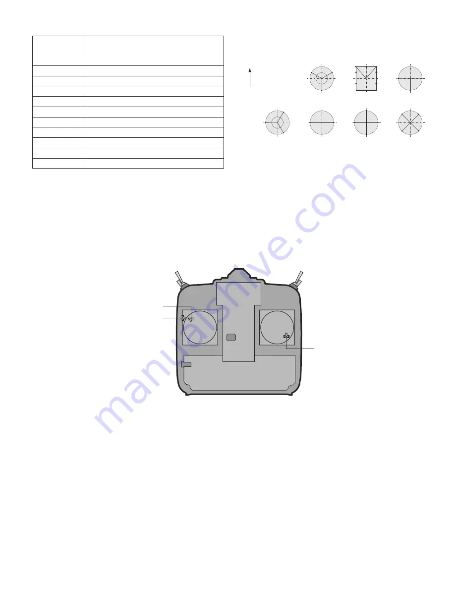
Mode 2 transmitter with rear cover removed.
Aileron
Elevator
Rudder
Stick
Stick
<RXPD\DGMXVWWKHWHQVLRQRI\RXUVWLFNVWRSURYLGHWKHIHHOWKDW\RXSUHIHUIRUÀ\LQJ7RDGMXVW\RXUVSULQJV\RX¶OOKDYH
to remove the rear case of the transmitter. First, remove the battery cover on the rear of the transmitter. Next, unplug the
battery wire, and remove the battery and RF module from the transmitter. While you are removing the RF module, pay
attention to the location of the pins that plug into the back of the module. Next, using a screwdriver, remove the four
screws that hold the transmitter’s rear cover in position, and put them in a safe place. Gently ease off the transmitter’s rear
FRYHU1RZ\RX¶OOVHHWKHYLHZVKRZQLQWKH¿JXUHDERYH


