42
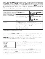
GOAL of EXAMPLE:
STEPS:
INPUTS:
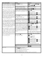
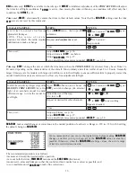
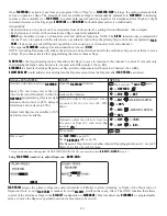
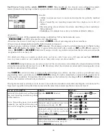
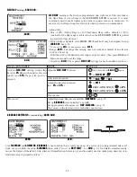
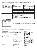
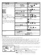
Activate twin aileron servos using
AIL-
DIFF
.
Note that the function defaults to no
difference in down travel vs. up travel.
If you want differential travel, simply
adjust each side. (Ex: 90%)
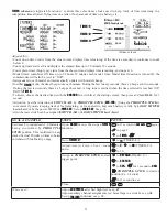
Open the
AIL-DIFF
function.
for 1 second.
(If
BASIC
,
again.)
C
to
AIL-DIFF
.
*
Activate the function.
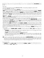
C
to
MIX
.
to
ACT
.
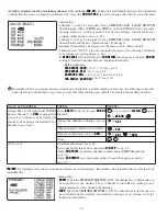
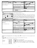
2SWLRQDO DGMXVW WKH XSGRZQ WUDYHO
separately for the 2 servos.
(Ex: adjust to
90%
.)
C
to
AIL1
.
AILERON STICK
.
to
90%
.
C
to
AIL2
.
AILERON STICK
.
to
90%
.
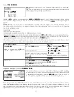
Close menu.
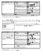
Where next?
Adjust individual servo's
SUB-TRIMs
: see p. 36 and
END POINTs
: see p. 27.
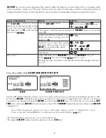
Set up
AIRBRAKE
mix: see p. 48.
Set up
ELEV-FLAP
PL[RQO\LIPRGHOKDVDÀDSVHUYRLQ&+VHHS
Set up
SNAP-ROLL
Function: see p. 45.
View additional model setups: www.
radiolink.com.cn/doce/
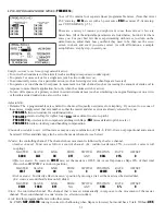
*If you receive an error message that
OTHER WING MIXING IS ON
, you must deactivate
ELEVON
or
FLAPERON
. See p. 43.
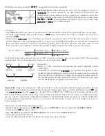
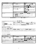
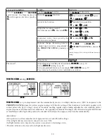
Using Twin Aileron Servos with a 5-channel receiver,
AILE-2
(
ACRO
GLID
):
AILE-2
allows
FLAPERON
and
AIL-DIFF
with a 5-channel receiver.
AILE-2
only tells
the radio that you are using CH5 and CH6 (
FLAPERON
), or CH5 and CH7 (
AIL-
DIFF
), not CH6 or CH7, as the second servo in
FLAPERON
or
AILE-DIFF
. You still
must activate and set up the
FLAPERON
AILE-DIFF
function.
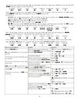
Note that selecting
CH6&5
or
CH7&5
does NOT free up CH6 or CH7 to be used for other functions when using a receiver
with more than 5 channels. Both 5 and 6 (
FLAPERON
AILE-DIFF
) are dedicated to the
FLAPERON
or
AILE-DIFF
programming.
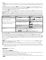
>7KLVLVEHQH¿FLDOZLWKIRXUDLOHURQVHUYRVWKDWQHHGWRKDYHWKHLUHQGSRLQWVRUVXEWULPVVHWVHSDUDWHO\&+&+DQG
CH6 are already fully set up to operate as ailerons. Mix CH7 or CH8 (the second aileron servo on the other side) into
ailerons to function properly.]
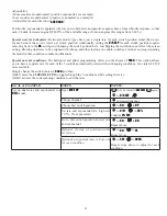
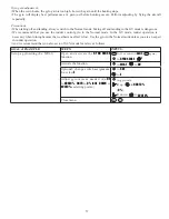
Aircraft tail types
(
ACRO
GLID
):
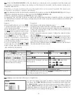
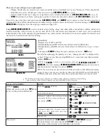
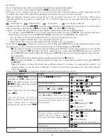
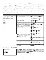
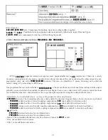
GOAL of EXAMPLE:
STEPS:
INPUTS:
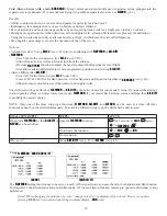
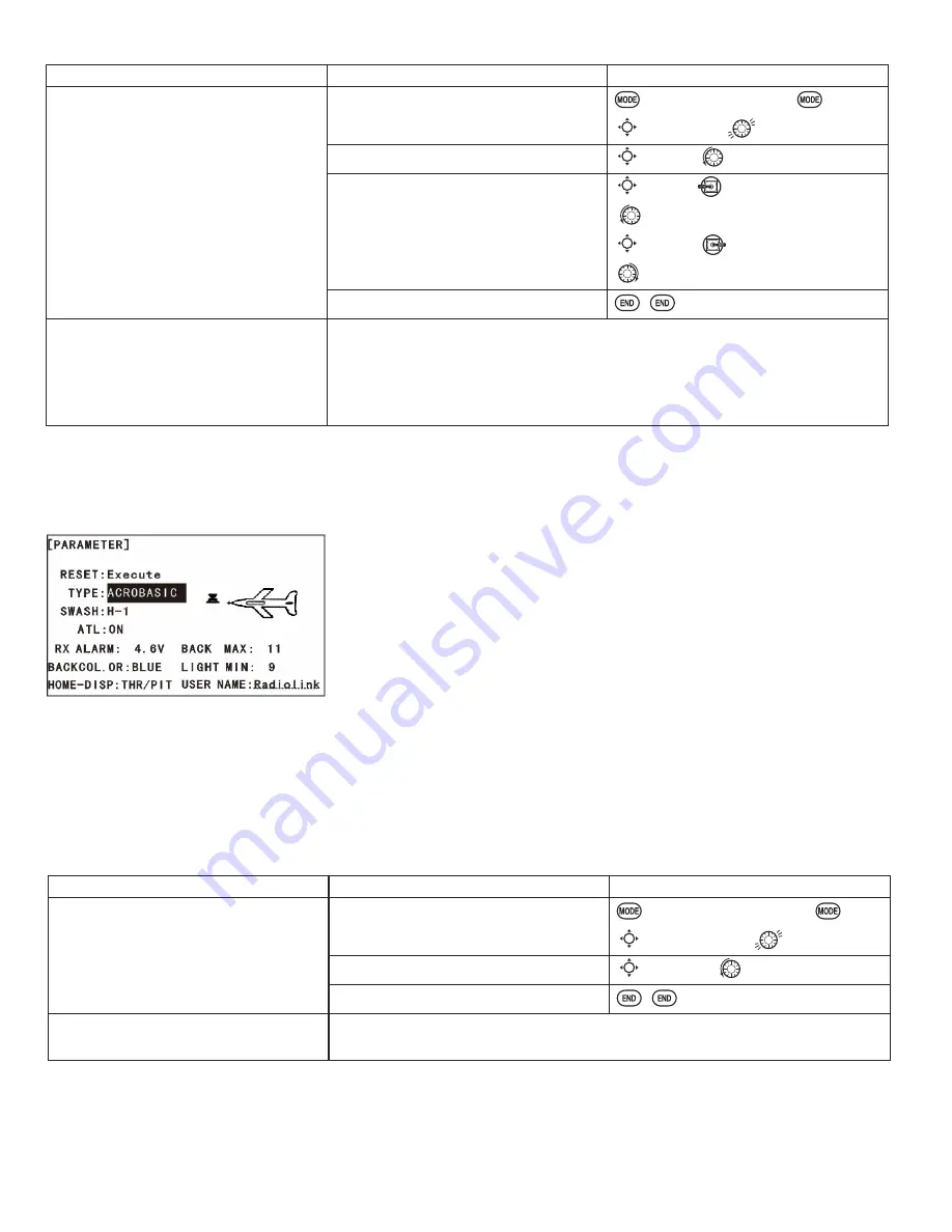
Adjust the second aileron servo output
from
CH6or7
to channels
CH6&5
.
Allows twin aileron servo operation
with a 5-channel receiver.
Open the
PARAMETER
submenu.
for 1 second.
(If
ADVANCE
,
again.)
C
to
PARAMETER
.
Select
AILE-2
and change to
CH6&5
.
C
to
AILE-2
.
to
CH6&5
.
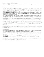
Close menu.
Where next?
Finish setting up
FLAPERON
or
AILE-DIFF
. see Twin Aileron Servos: p. 39.
View additional model setups on the internet: www.
radiolink.com.cn/doce
48.


