81
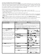
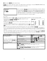
Revo. curves for idle-ups are often v-shaped to provide proper rudder input with negative pitch and increased throttle
GXULQJ LQYHUWHG ÀLJKW 5XGGHU LV QHHGHG WR FRXQWHU WKH UHDFWLRQ ZKHQHYHU WKHUH LV LQFUHDVHG WRUTXH ,Q LQYHUWHG ÀLJKW
throttle stick below half has increased throttle and negative pitch, therefore increasing torque and rotating the helicopter
unless the revo. mix is also increasing appropriately.)
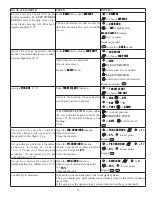
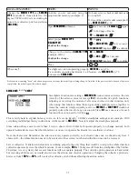
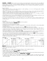
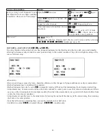
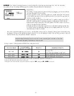
IDLE-UPS:
DGGLWLRQDO ÀLJKW FRQGLWLRQV DYDLODEOH VSHFL¿FDOO\ IRU KHOLFRSWHUV7KHVH DGGLWLRQDO ÀLJKW FRQGLWLRQV FRQWDLQ
different throttle curves, collective pitch curves, revo. mixing, and trims (except
IDLE-3
) to make the helicopter perform
certain maneuvers more easily. Lastly, the gyro and dual rate functions may be set to provide separate rates per condition
selected, including one for each idle-up.
2QHRIWKHPRVWFRPPRQÀLJKWFRQGLWLRQVFDQHDVLO\ÀLSIURPXSULJKWWRLQYHUWHGDQGEDFN7RGRVRWKHSLWFKFXUYHLVVHW
to 0 pitch at half stick, positive pitch (climb upright) above half, and negative pitch (climb when inverted) below half stick.
The throttle curve is adjusted to allow the engine to run consistently throughout the changes in pitch.
Additional idle-ups may be used to maximize the helicopter's flight characteristics in certain types of flight (i.e. fast
forward motion, backward) or maneuvers (loops, rolls, stall turns), or even the same maneuver but changing from heading-
KROG$9&6J\URPRGHWRQRUPDOJ\URPRGH7KH
AT10
SURYLGHVLGOHXSVWRDOORZWKHPRGHOHUDGGLWLRQDOVHWXSVDORQJ
ZLWKWKHQRUPDOÀLJKWFRQGLWLRQ1RWHWKDW
IDL3
does not include governor settings.)
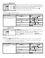
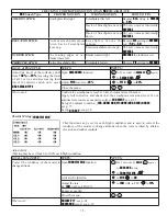
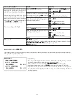
Adjustability:
•
SWITCH G
(
AT10
) or
E
(
AT
10) is programmed for normal (
NORM
), idle-up 1
(
IDLE-UP1
), and idle-up 2 (
IDLE-UP2
) curves.
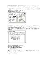
Adjustable in the
CONDITION SELECT
(
IDLE-UP1/2
,
IDLE-UP3
items).
(
IDLE-UP1/2
3-position type switch only,
IDL3
2-position type switch only)
• Activated with the throttle curve for that condition in
THR-CURVE
.
• Curves are adjusted to maintain constant RPM even when the collective pitch
is negative (inverted).
• Note that
REVO
.mixing has one curve for idle-ups 1 and 2 and a second curve just for idle-up3.
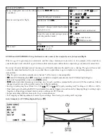
•Gyro settings may be set separately for each idle-up. (See p.
*RYHUQRU VHWWLQJV PD\ EH VHW XS WR IROORZ 1RUPDO,GOH,GOH EXW GR QRW RIIHU D VHWWLQJ WR DGMXVW IRU HDFK RI WKH
conditions like gyro. (See p. 81.)
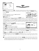
• Activating
OFFSET
makes the
TRIM LEVERS
adjust the trim separately in each of the idle-up conditions.
For an example of throttle and pitch curves and revo, please see Normal Flight Condition Setup, p. 78.
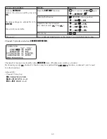
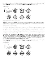
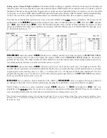
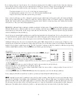
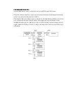
Revo. mixing rates are 5-point curves. For a clockwise-turning rotor, the rudder is mixed in the clockwise direction
when collective pitch is increased; for counterclockwise-turning, the opposite. Change the operating direction setting by
changing the signs of the numbers in the curve from plus (+) to minus (-) and vice versa. Suggested defaults:
Clockwise rotation: -20, -10, 0, +10, +20% from low throttle to high.
Counterclockwise rotation: +20, +10, 0, -10, -20% from low throttle to high.
Adjust to the actual values that work best for your model.
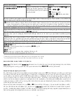
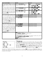
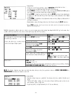
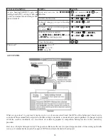
OFFSET
: Optional separate trims in addition to those for the normal condition. This function is used to automatically change
WKH WULP RI D KHOLFRSWHU IRU H[DPSOH ZKHQ WUDQVLWLRQHG IURP KRYHU WR À\LQJ DW KLJK VSHHG$ FORFNZLVHURWDWLRQ URWRU
helicopter tends to drift to the right at high speed, so an aileron offset may be applied to offset the helicopter to the left.
The necessary elevator offset varies with model geometry, so it must be determined by noting collective pitch changes at
high speed. The rudder offset is affected by both revo. mixing and trim lever movement while in the offset function.
81

