87
GOVERNOR
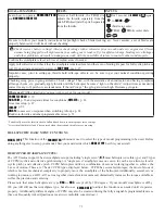
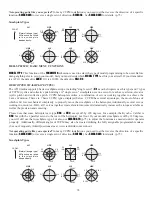
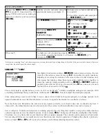
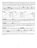
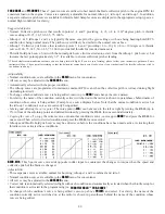
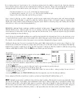
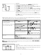
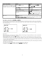
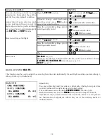
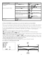
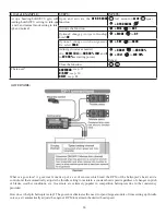
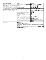
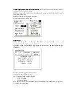
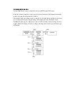
: The Governor mixing function is used to adjust the Governor speed settings (rS1, rS2, rS3) from the
transmitter. (If you are using a different governor, follow the manufacturer's instructions.)
Adjustability:
2QRIIPD\EHVHSDUDWHIURPVSHHGVZLWFKLQJE\SOXJJLQJJRYHUQRURQRIILQWR
ch8 and changing CUT-CH setting.
,I XVLQJ VHSDUDWH RQRII VZLWFK DVVLJQPHQW LV WRWDOO\ DGMXVWDEOH %H FDUHIXO
not to assign governor off to a condition switch if you want the governor to
function in that condition.
6SHHGVZLWFKLQJDQGJRYHUQRU212))PD\EHWRJHWKHUXVLQJRQHVZLWFKRU
212))VZLWFKLQJPD\EHSHUIRUPHGXVLQJDQLQGHSHQGHQWVZLWFKFKDQQHO
:KHQVSHHGVHWWLQJFRQWUROXVHV&+DQGVHSDUDWH212))VZLWFKLVQRWXVHG
CH8 can be used for other functions.
,QÀLJKWDGMXVWPHQWRIWKHKHDGVSHHGIRUHDV\DGMXVWPHQWGXULQJWXQLQJPD\
be created using an additional channel and a programmable mix. See www.
radiolink.com.cn/doce
for details.
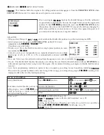
The GV-1 controls throttle when it is active, so the throttle will not obey any FailSafe settings preset for throttle in the
WUDQVPLWWHU$OZD\VVHWWKH)DLO6DIHVHWWLQJIRUWKH*9¶VRQ RIIFKDQQHOWR2))7KLVZD\WKHJRYHUQRULVVKXWRII
and the throttle obeys the FailSafe throttle commands.
Expert Tip:
Mounting the Governor to the counter gear instead of the fan
GUDPDWLFDOO\VLPSOL¿HVLQVWDOODWLRQLQPDQ\PRGHOV
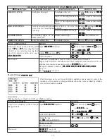
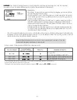
Setting example:
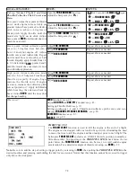
:KHQVSHHGDQG212))DUHXVLQJRQHVZLWFK
Governor Speed
Switch Position
(
Switch C
or Cond.)
Rate (%)
Adjustment from Tx.
RS1: OFF
UP
or
NORM
0
Use up to 0%.
(Governor speed display reads “off”.)
RS2: 1400
CNTR
or
IDL1
50
Speed adjusted by raising and lowering rate.
RS3: 1700
DOWN
or
IDL2
100
Speed adjusted by lowering rate.
*The relationship of the governor speed setting rS1~rS3 and the switch positions conforms to the table above.
*In throttle hold, always check that the governor is off.
*If the speed value rises when the cut switch is activated, reverse the “
DIR
” setting from
UP
to
DOWN
or vice versa.

