background image


10 


RadioLink Electronic Ltd
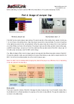
                                                                                                                                   

www.radiolink.com


Jumper Cap 1&2 

Operation Mode 

Pull inward 

Neutral 

position 

Push forward 

Both removed 

Normal mode 

Forward 

No operation 

Reverse 

Jumper Cap 1 

inserted only 

Brake mode 

Brake/Reverse 

Jumper Cap 2 

inserted only 

Racing mode 

Brake 

Both inserted 

Climbing mode 

Brake 

Reverse 


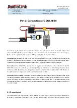
Normal mode: Pull the trigger inward for forward operation, and push the trigger forward for backward operation. 

There is no brake for the transition between going forward and backward. With low heat, this mode is suitable 

to use in confined spaces. 


Brake mode: It is the common mode. Pull the trigger inward for forward operation. When the operation of the 

trigger is changed from pulling inward to pushing forward, the ESC will perform the brake operation. Return 

the trigger to the neutral position currently, and then push the trigger forward again. The ESC will perform the 

reverse operation.   


Racing mode: Pull the trigger inward for forward operation, and push the trigger forward for brake operation. 

There is no reverse operation on ESC.


Climbing mode: Pull the trigger inward for forward operation, and push the trigger forward for reverse operation, 

When the trigger is at the neutral position, the ESC will perform the brake operation.
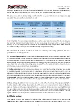


Battery Type 

When using different types of batteries, change the state of Jumper cap 3 to make the battery type match the 

actual battery. Insert Jumper cap 3 when using a lithium battery, and remove Jumper cap 3 when using a non-

lithium battery. Wrong state of Jumper cap 3 may cause serious over-discharge of the battery and damage the 

battery. Be sure to check Jumper cap 3 to confirm the battery type of the ESC before use. 
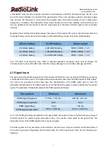
 

BEC output 

Different servos may have different requirements for the working voltage. Change the state of the Jumper cap 

4 to select the BEC output voltage. You can choose the appropriate BEC output voltage according to the use 

requirements of the connected equipment. Remove Jumper cap 4 when using a common 5V servo, and BEC 

will output 5.5V voltage. Insert Jumper cap 4 when using high voltage servo, and BEC will output 7.5V voltage. 

Be sure to check Jumper cap 4 to confirm the right BEC output voltage before use. Otherwise, wrong BEC 

output voltage selection may damage the servos.   
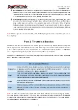
 

Part 5. ESC status


COOL 9030 ESC has two indicator lights, red and green, to display the current operating status of the ESC. 

The power light is used to indicate the current self-check and power supply status of the ESC system, and the 

color of the light is green. The status light is used to indicate the current self-check and operating status of the 

ESC system, and the color of the light is red. At the same time, the indicator lights have three states: on, off 

Summary of Contents for COOL 9030

Page 1: ...ehicles Drift Cars Crawlers Trailers Bait Boats Rescue Boats Surveying Boats Note This manual only introduces the basic usage of RadioLink COOL 9030 brushed ESC For more information such as tutorials and FAQ please access to RadioLink website www radiolink com or send mail to after_service radiolink com cn ...

Page 2: ... 3 1 1 COOL 9030 Overview 3 1 2 Specifications 4 Part 2 Connection of COOL 9030 5 2 1 Power Input 5 2 2 Motor output 6 2 3 Signal input 7 Part 3 Throttle calibration 8 Part 4 Usage of Jumper Cap 9 Part 5 ESC status 10 5 1 Motor sound 11 5 2 Indicator light 11 5 3 Mixed prompt of motor and light 12 Thanks 12 ...

Page 3: ...nected for a long time without use the battery will eventually be completely discharged which will cause the malfunction of the battery or ESC RadioLink is not responsible for any damage caused by incorrect operation Part 1 Introduction of COOL 9030 1 1 COOL 9030 Overview Power input The power input of the ESC is connected to the power supply At the same time the voltage range of connected power s...

Page 4: ... input power supply and the output voltage of BEC Details will be introduced later LED light description Power light The power light is used to indicate the current self check and power supply status of the ESC system The color of the light is green Details will be introduced later Status light The status light is used to indicate the current self check and operating status of the ESC system The c...

Page 5: ...There is no positive or negative connection between the brushed motor and the ESC If the motor turns incorrectly you can directly change the direction of the motor through the servo phase in the menu of the transmitter or exchange the connection of the two motor output cables of ESC Make sure the right connection and good contact between the motor and the ESC Connection to the battery The battery ...

Page 6: ...rotection state and the battery voltage rises back to the half power protection value the system will exit the under voltage protection state Then the system will return to normal operation and the normal output control of the motor is restored Half power protection It is half power output protection state When the voltage of the input power supply is lower than the value the ESC will reduce the o...

Page 7: ...oncrete cases to prevent the ESC and motor from being damaged or even battery damage accidents 2 3 Signal input The signal input the throttle signal input of this brushed DC ESC can only identify the PWM signal output by a single channel of the receiver The signal with multiple channel codes such as PPM signals S BUS signals etc cannot be recognized At the same time the characteristics of the PWM ...

Page 8: ...ote controller such as servo output ratio and servo midpoint value etc Calibrate the throttle at this time so that the ESC can be adjusted to the signal output of the receiver to achieve the expected effects COOL 9030 is a two way ESC so the throttle calibration method is the same as that of the common two way ESC The specific steps are as follows ESC Calibration Method Preparation Connect the ESC...

Page 9: ... output voltage Jumper cap 1 and 2 are used to set the operation mode of the ESC Jumper cap 3 is for battery type and jumper cap 4 for BEC output voltage The different states of the 4 sets of jumper caps will correspond to the different operation modes of the ESC Choose the operation mode you need determine the type of the battery you use and the requirements for the BEC Then refer to the followin...

Page 10: ...Type When using different types of batteries change the state of Jumper cap 3 to make the battery type match the actual battery Insert Jumper cap 3 when using a lithium battery and remove Jumper cap 3 when using a non lithium battery Wrong state of Jumper cap 3 may cause serious over discharge of the battery and damage the battery Be sure to check Jumper cap 3 to confirm the battery type of the ES...

Page 11: ...check battery type report and operation allowed in sequence as shown in the table below If the sound of the motor is incomplete when the ESC starts inspect the ESC and the equipment connected Motor Sound ESC status Tone beep Do Re Mi Self check finished Short beep Battery type report Long beep Operation allowed Note There are three consecutive tones Do Re Mi in tone beep state of the motor The num...

Page 12: ...ht are as follows Motor sound and red indicator light System state Four consecutive short beeps System high temperature warning Above 85 Flash once every 0 2 second Three consecutive short beeps System low temperature warning Below 40 Flash once every 0 4 second One short beep Throttle signal loss Flash once every 0 6 second Two consecutive short beeps Abnormal throttle signal Flash once every 0 8...

Reviews: