
5
RadioLink Electronic Ltd
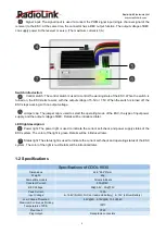
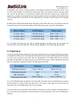
Motor Limit:
Brushed Motor Limit with 380/540/550
Internal Resistance:
7 milli-ohm
Drive Frequency:
PWM frequency 2KHz
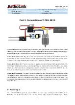
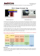
Part 2. Connection of COOL 9030
Connect the signal cable of the ESC with the receiver correctly before use. Then connect the motor output
cable of the ESC with the motor accurately (You can choose the connection direction based on actual usage.).
Make sure the negative and positive poles of the power input cable are not reversed.
Connection to the receiver
: Plug the receiver connection cable of the ESC into the throttle channel of the
receiver. The receiver connection cable of the ESC outputs the voltage of 5.5V to the receiver and the servo,
so please do not supply additional power to the receiver. Otherwise, the ESC may be damaged.
Connection to the motor
: There is no positive or negative connection between the brushed motor and the
ESC. If the motor turns incorrectly, you can directly change the direction of the motor through the servo phase
in the menu of the transmitter, or exchange the connection of the two motor output cables of ESC. Make sure
the right connection and good contact between the motor and the ESC.
Connection to the battery
: The battery connection cable of the ESC has positive and negative poles. When
connecting the battery, please make sure that the (+) positive pole of the cable is connected to the (+) positive
pole of the battery, and the (-) negative pole is connected to the (-). If the ESC is connected reversely, it will
be damaged. Warranty service will not be provided if the ESC is damaged due to the reverse connection of
the power supply.
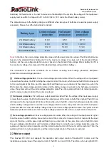
2.1 Power Input
This brushed DC ESC supports two types of batteries as power supply, including non-lithium batteries( NI-
MH battery, nickel-cadmium batteries and lead-acid batteries, etc.) and lithium batteries(polymer lithium


