

6
RadioLink Electronic Ltd
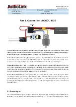
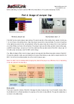
batteries). At the same time, in order to make sure the stability of the system, the voltage of the input power
supply must be within the range of 6.0V to 16.8V (6V to 18 V under the lithium battery mode).
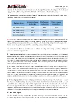
The protection ways to the battery voltage are different when two types of batteries are used as power supply
separately. Please check the below table for details:
Battery type
Under-voltage
protection
Half-power
protection
Over-voltage
protection
2S lithium battery
6.0 V
6.5 V
8.7 V
3S lithium battery
9.0 V
9.75 V
13.05 V
4S lithium battery
12.0 V
13.0 V
17.4 V
Non-lithium battery
6.0 V
6.5 V
16.8 V
Note
: In the table, the under-voltage protection value and half-power protection value of the lithium battery are
based on the standard lithium battery (4.2V is the maximum voltage of a single cell of the standard lithium
battery), but the over-voltage protection value is based on the standard high-voltage lithium battery (4.35V is
the maximum voltage of a single cell of the standard high-voltage lithium battery).
The introduction of the three conditions are as follows, including under-voltage protection, half-power
protection and over-voltage protection.
①
Under-voltage protection
: It is an under-voltage protection state. When the voltage of the input power
is lower than this value, the ESC will stop the output control of the motor, which means the ESC will not respond
to the input signal at this time, and the power light will flash to give a reminder. At the same time, when the
ESC enters the under-voltage protection state and the battery voltage rises back to the half-power protection
value, the system will exit the under-voltage protection state. Then the system will return to normal operation,
and the normal output control of the motor is restored.
②
Half-power protection
: It is half-power output protection state. When the voltage of the input power supply
is lower than the value, the ESC will reduce the output power of the motor to half of the original (The ESC can
still respond to the input signal at this time). Meanwhile, when the ESC enters the half-power protection state
and the battery voltage rises to near the over-voltage protection value, the system will not exit the half-power
protection state. But when the battery voltage drops to the under-voltage protection value, the system will exit
half-power protection state and enter the under-voltage protection state, with no output control of the motor.
③
Over-voltage protection
: It is over-voltage protection state. When the voltage of the input power is higher
than this value, the ESC will stop the output control of the motor, which means it will not respond to the input
signal at this time, and the power light will flash to give a reminder. At the same time, when the ESC enters
the over-voltage protection state and the battery voltage drops to below the over-voltage protection value, the
system will resume normal operation and the normal output control of the motor will be restored. Then the
system will return to normal operation, and the normal output control of the motor is restored.
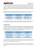
2.2 Motor output
This brushed DC ESC only supports the operation and output control of brushed DC motors, and the
instantaneous peak value of the output current of the ESC can reach 100A. Therefore, when using this ESC,


