background image

RadioLink  Electronic  Limited 

www.radiolink.com


 14 

Chapter 5 Image Transmission of F121 


The image transmission device of F121is 5.8G 25mW all-channel camera integrated image transmission. If it

’s 

the  image transmission  version  purchased, the  binding  between  F121  and  the  FPV screen  has  been  done by 

factory  default.  Pilots  only  need  to  power  both  on  before  flight.  If  it

’s the standalone version of F121, an FPV 

screen  or  a  goggle  with  integrated  5.8G  image  transmission  receiver  is  needed  and  setup  by  following  its 

instructions. 

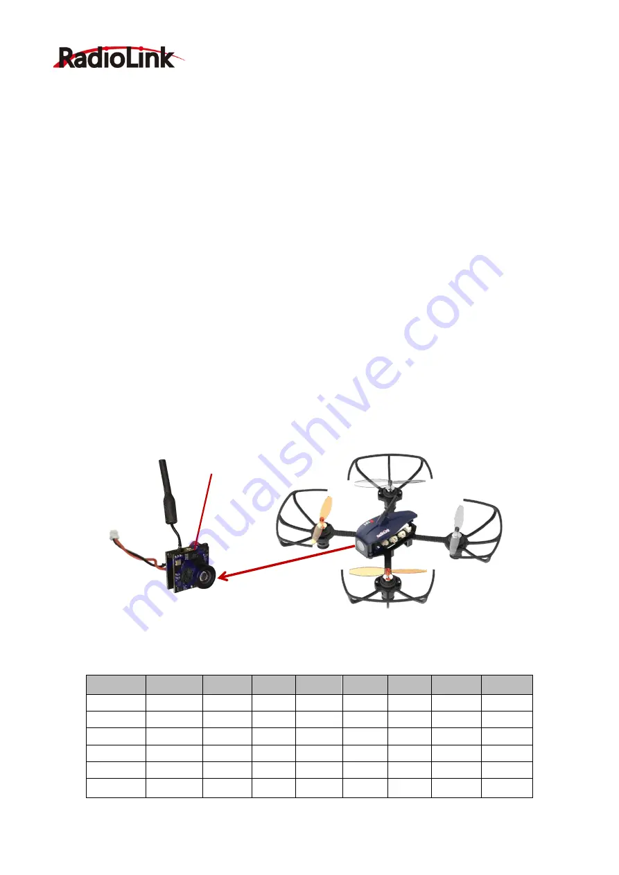
The default transmission power is 25MW. Available power among 25MW,100MW and 200MW can be changed 

by pressing the button on the camera. More instructions about setting the power, please visit 

www.radiolink.com


for detailed manual. 

Note

  As  device  of  image  transmission  includes  transmit  and  receive,  the  distance  could  be  influenced  by  the 

gain of transmit and receive.   

Definition of the image transmission led indicator 


RED and BLUE(and YELLOW) always on means normal working status. 


If RED(and YELLOW) 

is always on while BLUE is off, meaning it’s at PitMode. That is, transmission off. 

The transmission distance is 1-

2m. It’s advised to choose this mode if there are many people switching channels 

simultaneously at the same space so that channe

ls won’t get mixed. 

Customize the power and the channel frequency


After powering on, wait for 10 seconds to initialize, red and blue(and yellow) always on means normal working 

status. Long press the channels/power switching button, the channel frequency, the channel team and the 

transmit power will recycle. 


Table of Band/Frequency 


Band/Freq


5865M 

5845M  5825M  5805M  5785M  5765M 

5745M 

5725M 

5733M 

5752M  5771M  5790M  5809M  5828M 

5847M 

5866M 

5705M 

5685M  5665M  5645M  5885M  5905M 

5925M 

5945M 

5740M 

5760M  5780M  5800M  5820M  5840M 

5860M 

5880M 

5658M 

5695M  5732M  5769M  5806M  5843M 

5880M 

5917M 

5362M 

5399M 

5436M  5473M  5510M  5547M 

5584M 

5621M 

*The cover of F121 needs to be removed when pressing the button 


Channels/Power Switching Button


Summary of Contents for F121

Page 1: ...Drone Altitude Hold by Inertial Navigation User Manual Please be kindly noted that this manual will be updated regularly and please visit RadioLink official website to download the latest version www radiolink com V 1 0 ...

Page 2: ...speed rotation eg Propellers brushed motors After landing off make sure the aircraft is disarmed and propellers have stopped moving before getting close to touch the aircraft Always be sure about turning off the receiver powering off the aircraft before the transmitter Follow the instructions of propellers installation in case of dropping during flight To ensure the best radio communication please...

Page 3: ...tallation 5 3 2 Propellers Installation 5 3 3 Power On F121 6 3 4 Flight Note 6 3 5 Setup Compatible Transmitters 7 3 6 Binding 8 3 7 Arm and Disarm F121 9 Chapter 4 Flight at Different Flight Modes 10 4 1 Altitude Mode Rise Descend 13 4 2 Altitude Mode Hover 13 4 3 Altitude Mode Forward Backward Right Left 13 4 4 Altitude Mode Clockwise Anticlockwise Rotation 13 4 5 Stabilize Mode 13 Chapter 5 Im...

Page 4: ...at high speed and Stabilize beginners can flight stably at the first trial F121 is monitored by RadioLink mini racing drone flight controller F121 which is different from other flight controllers with PID needs to be set before use will tune automatically The software noise reduction technology not only enables a more pleasant flight but also makes the motors more responsive and more efficient tha...

Page 5: ...d be NO higher than 5V 2 2 Transmitter The two joysticks of T8S correspond to the four basic channels respectively The below example takes RadioLink radio T8S Mode 2 Throttle on the left stick Left joystick Make the F121 rise or descend by toggling the left stick THROTTLE vertically upward or downward and turn clockwise or anticlockwise by toggling the left stick YAW to the left or right Right joy...

Page 6: ...p CCW 65 mm prop CCW motor CW 8 520 motor CW protector Prop protector Motor protector 65mm prop CW 8520 motor CCW Prop protector Motor protector 65mm 8520 Prop Motor protector Camera Camera protector F121 flight controller Fiber Frame Cable receiver flight controller Battery frame R8SM receiver PA1 7 8 Screws F121 cover CW Clockwise CCW Counter Clockwise There are screws packed with F121 to ensure...

Page 7: ...scends If at Alt Hold Mode toggle the throttle stick vertically upward till the F121 rises to the preferred height then toggle back to center position and release the F121 will remain at this height B Yaw Clockwise Anticlockwise Toggle the yaw stick on the left to the left and F121 will turn anticlockwise and toggle the yaw stick to the right then F121 turns clockwise Yaw stick to the left F121 tu...

Page 8: ...ically downward then F121 flies backwards D Roll Right Left Toggle the roll stick on the right to the left and F121 will fly to the left side and toggle the roll stick to the right then F121 will fly to the right side Pitch stick upward F121 moves forward Pitch stick downward F121 moves backward Roll stick to left F121 flies to the left side Yaw stick to the right F121 turns clockwise ...

Page 9: ...RadioLink Electronic Limited www radiolink com 6 Roll stick to right F121 flies to the right side ...

Page 10: ...ion F121 is installed WITHOUT propellers protector by factory default because of the package consideration To ensure a safety flight it s strongly advised to check if the protectors are well installed Find the two notches respectively on the motor protector and propeller protector as image on the right Put on the propeller protector from the bottom and adjust the position of the notches correspond...

Page 11: ...e the four motors are vertical to the aircraft frame Adjust them to vertical positions if necessary otherwise F121 may not flight successfully 3 3 Power On F121 Before powering on F121 fully charge the 1S LiPo battery first Plug the PH2 0 end of the battery into the F121 then insert the battery into the battery frame under at the bottom of F121 1 Orange propellers indicates the head of F121 by def...

Page 12: ...d while RTF version is packed with the transmitter T8S and receiver R8SM combo Receiver R8SM is also compatible with RadioLink T8FB If it s RadioLink transmitter AT10 AT10II AT9 AT9S AT9S Pro used with F121 compatible receiver should be R6DSM If it s transmitters of other brands used compatible receiver chosen should capable of supporting SBUS output T8FB T8S RadioLink 8 channel transmitter are we...

Page 13: ...se the binding is complete with receiver R8SM installed by factory default However if it s only the aircraft F121 is purchased binding between the transmitter and F121 with receiver installed needs to done first If fly F121 with RadioLink transmitter and receiver binding steps are same as following Place the transmitter and receiver installed on F121 close to each other within 50 centimeters Power...

Page 14: ...ransmitter of AT9S Pro AT9S AT10 AT10II used channel quantity needs to be set first in order to be compatible with receiver R6DSM Long press MODE to enter BASICE MENU select SYSTEM and modify CH SELECT as 10CH Otherwise F121 won t be able to be armed 3 7 Arm and Disarm F121 A How to arm Throttle on left Mode 2 Toggle the left joystick to the lower right corner and hold this position for 3 seconds ...

Page 15: ...arm Throttle on left Mode 2 Toggle the left joystick to the lower left corner and hold this position for 3 seconds till the green LED of F121 is off Throttle on right Mode 1 With right joystick at bottom toggle the left stick to the left and hold this position for 3 seconds till the green LED of F121 is off The green LED of F121 off means it is disarmed with success Channel 4 to left ...

Page 16: ...tick as soon as toggle to one direction so that F121 will back to level automatically Otherwise F121 will keep flying to the toggled direction with accelerated speed 4 4 Altitude Mode Clockwise Anticlockwise Rotation When get familiar with the above flights try flight clockwise anticlockwise because the yaw practice is more difficult to judge the flight direction Clearly knowing the direction will...

Page 17: ... the image transmission led indicator RED and BLUE and YELLOW always on means normal working status If RED and YELLOW is always on while BLUE is off meaning it s at PitMode That is transmission off The transmission distance is 1 2m It s advised to choose this mode if there are many people switching channels simultaneously at the same space so that channels won t get mixed Customize the power and t...

Page 18: ...he red and blue leds always on means setting saved then normal working status Otherwise the setup mode remains and all the parameters set above can t be saved with success Note When installing the image transmission make sure the heat radiation is considered Otherwise the transmission power will decrease even turn off as the protection of over heating is activated It s normal that the camera will ...

Page 19: ...w radiolink com 16 Low Voltage Alarm Green led flashes quickly when lower than 3 8V Control Distance 2KM in the air Maximum range is tested in an unobstructed area free of interference Thank you again for choosing RadioLink products ...

Reviews: