background image

RadioLink Electronic Limited

www.radiolink.com

33

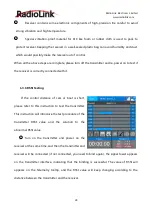
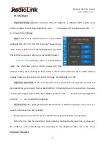
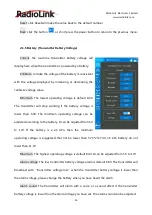
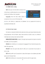
The decreased time can be set by one-second steps.

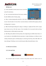
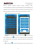
Setting steps: turn on your RC8X, click the button

at the left bottom of RC8X into

System menu, or click the blue select box named Backlight to set the LCD brightness.

Reset: click Reset will make the value back to the default number.

Back: click the button

or short press the power button to return to the previous menu.
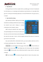
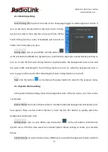
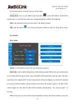
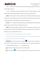
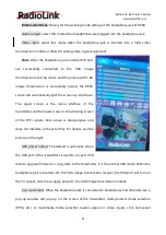
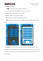
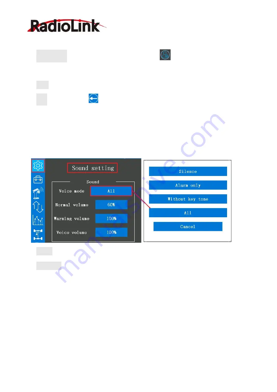
2.1.4 Sound

Voice mode:

Silence: turn off all the sound if the voice mode select silence.

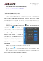
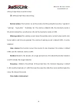
Alarm only: only broadcast the warning notes that have preset. When the current value same

as or smaller than the preset alarm value, the RC8X will broadcast the warning notes, the other

operation such as press switch or tap function button will do not trigger any sounds. For example:

you have set the transmitter will alarm with sound when the receiver signal is -85 dbm, if the

current signal is or less than -85 dbm, the transmitter will broadcast “low receiver signal” to

warning.

Without key tone: no voice when press the switches and tap the function buttons only. The

Summary of Contents for RC8X

Page 1: ...RC8X FHSS 8 Channel Digital Proportional RC System Adaptable to RC Cars Boats Robots Instruction Manual 2022 09 ...

Page 2: ...smitter Low Voltage Alarm 16 1 2 10 Compatible Receivers of RC8X 17 1 3 Receiver Introduction 18 1 3 1 Features of R8FG 18 1 3 2 Binding 18 1 3 3 Receiver Connection 19 1 3 4 Signal Mode and Gyro Function of R8FG 23 1 3 5 Installment of Receiver Antenna 27 1 3 6 RSSI Testing 28 2 RC8X Basic Functions 29 2 1 System menu setting 29 2 1 1 Desktop setting 30 2 1 2 System theme setting 30 2 1 3 Backlig...

Page 3: ... safe 72 2 3 9 Acceleration 73 2 3 10 Condition 74 2 3 11 Idle up 75 2 3 12 D R ATL 76 2 3 13 Channel limiter 78 2 3 14 Channel setting 79 2 4 Telemetry menu 81 2 4 1 Sensor list 81 2 4 2 Sensor setting 81 2 4 3 Voice 84 2 5 Racing curve 85 2 5 1 Steering curve 85 2 5 2 Throttle curve 88 2 5 3 Brake curve 91 2 5 4 Steering speed 92 2 5 5 Throttle speed 94 2 5 6 Traction control T R C 98 2 5 7 A B ...

Page 4: ...me 137 2 9 2 Language 137 2 9 3 Reset system settings 138 2 10 Modifying for Left hand Use 139 2 10 1 Remove the Wheel 139 2 10 2 Remove the Wheel Installation Port Cover 140 2 10 3 Install Wheel 141 2 10 4 Install the Wheel Installation Port Cover 142 2 11 Wheel or Trigger Mechanical Adjustment 144 2 11 1 Trigger brake lever adjustment 144 2 11 2 Trigger tension screw adjustment 145 2 11 3 Trigge...

Page 5: ...0 and battery properly charged before connecting the receiver 5 Always check the throttle trigger on the transmitter to be sure it is at the neutral position before turning on the power switches of transmitter and receiver Always be sure the engine is not running or the motor is stopped before turning off the power switches 6 Make sure that turn on the transmitter power switch and then turn on the...

Page 6: ...e influence of alcohol or drugs Your judgment is impaired and could result in a dangerous situation that may cause serious injury to yourself as well as others 11 Do not touch the engine motor speed control or any part of the model that will generate heat while the model is operating or immediately after its use These parts may be very hot and can cause serious burns 1 1 2 Safety Guidelines for SD...

Page 7: ...tter without one code to modify Multiple Programmable Mix Control such as 4WS 4WD Tank mixing Tilt mixing CPS mixing etc RC8X with steering curve throttle curve brake curve etc that is an ideal partner for all types RC cars and boats in the market including single engine and twin engine models such as Crawlers Tanks Caterpillars Basher RC Short Course Truck RC Crawler Drifting RC Car Gasoline RC C...

Page 8: ...y or a 6S Ni MH battery Antenna Built in Antenna Frequencies Band 2 4GHz ISM ISM band 2400MHz 2483 5MHz Modulation Mode GFSK Transmission Power 20dbm Spread Spectrum FHSS 67 channels pseudo random frequency hopping Channel Resolution 4096 with regular jitter of 0 5us Low Voltage Alarm low transmitter voltage low receiver voltage low model battery voltage or low RSSI alarm can be customized Dimensi...

Page 9: ...nd 600 meters 1968 5ft Maximum range tested in unobstructed areas free of interference Operating Current 30mA Operating Voltage 3 12V Signal Output SBUS PPM PWM Compatible Transmitter RC8X RC6GS V3 RC6GS V2 RC6GS RC4GS V3 RC4GS V2 RC4GS T8FB T8S EXT Connect Cable 1 Type C Cable for Upgrade Manual 1 Packing Box 1 RC8XTransmitter 1 R8FGreceiver 1 4G SD Card 1 Lanyard 1 ...

Page 10: ...ely You can enter the AliExpress Official Store to purchase Or login to the Radiolink official website www radiolink com for product details FPV monitor holder R7FG Receiver with Gyro Built in R6FG Receiver with Gyro Built in R6F Receiver support R8F Receiver 2 way Transmission R4FGM mini Receiver R4F mini Receiver ...

Page 11: ...RadioLink Electronic Limited www radiolink com 10 1 2 5 Buttons Introduction ...

Page 12: ...press backward the button to decrease the value Restoration to factory settings by push the buttons moving to the left horizontal direction DT2 Digital Trim 2 default throttle trim DT3 Digital Trim 3 Default dual rate DT4 Digital Trim 4 Default brake1 rate ATL DL1 Digital Dial 1 Code switch Gyro gain PS1 Push Switch 1 Default control CH4 can be programmed Self locking switch or trigger switch can ...

Page 13: ...ogrammed PS5 Push Switch 5 Default control CH5 can be programmed VR Knob switch Dial default control CH3 can be programmed HOME Power switch Switch for quick back to homepage ATL Adjust Throttle Low Default brake rate 1 2 7 Icon Introduction Into Setting Menu Mixing Menu System Menu Model Select Menu Tools Menu SD Card Folder Basic Menu Transmitter Version Information Telemetry Menu Back To Previo...

Page 14: ...es vital components are protected from a reverse polarity connection 1 AAA Battery remove the battery cover from the transmitter by sliding it in the direction of the arrow follow the picture at right load 8 pieces new AAA batteries Pay attention to the polarity markings make sure the 8 pieces AAA batteries are not loose Slide the battery cover back onto the case 2 LiPo Battery remove the battery ...

Page 15: ... Radiolink Logo and the welcome to Radiolink sound is emitted at the same time the home page will display this information as the picture below 1 The current model name There are 100 models in total can be select in Model select menu Make sure the model s name on the display is consistent with the actual model before running If the model s name is not consistent with the actual model the movement ...

Page 16: ...al uptime of the transmitter Turn off the transmitter will not affect time accumulation T2 Click to time Click the T2 timer functional block to start to time stop to time or reset Click once to start to time click twice to stop to time click thrice to reset The timer set steps can follow 2 3 4 Timer 7 Telemetry RX the current input voltage of receiver EXT the current input voltage of cars or boat ...

Page 17: ... language can be changed in Information Menu Setting Steps turn on your RC8X click the button at the left bottom of RC8X into System menu click at the left of RC8X into Information menu click the blue select box below the word Language Chinese English can be chosen Back click the button or short press the power button to return to the previous menu 1 2 9 Transmitter Low Voltage Alarm Transmitter l...

Page 18: ...e button or short press the power button to return to the previous menu Attention the other parameter setting steps in the Battery menu can follow 2 1 5 Battery Transmitter Battery Voltage 1 2 10 Compatible Receivers of RC8X RC8X is packed with a R8FG receiver by default RC8X is also compatible with 8 channels receiver R8F capable of real time transmission of RSSI receiver and model voltage 7 chan...

Page 19: ...nd Gyro Function of R8FG 1 3 2 Binding RC8X and R8FG have finished binding by default So it s unnecessary to rebind when you received the new RC8X Turn on the RC8X and the R8FG the signal tower will show on the top of the screen as the picture below it means the transmitter and receiver have get ready to connect the ESC servo motor and other equipment that you are prepared for your car or boat But...

Page 20: ...g is complete and there will be a signal tower shown on top of the LCD screen of the transmitter If not succeed the LED will keep flashing slowly to notify repeat the above steps Note NO gyro by default as factory setting Since integrated gyro in R8FG will self check it is very important to remain R8FG still when powering it on green LED always on indicates normal working mode while green red LEDs...

Page 21: ...3V 12V When the receiver uses a separate battery for independent power supply the receiver will not be damaged if the battery polarity is reversed but if the servo is connected at this time it will cause damage to the servo 1 3 3 2 How to Connect R8FG Correctly for Telemetry R8FG supports telemetry of model battery voltage receiver voltage and RSSI The model voltage will display by connecting the ...

Page 22: ...tery connected to Telemetry port is only for 2S 6S battery voltage telemetry R8FG should be powered supplied by connecting to the CH2 pins on right Attention Reverse polarity protection circuit design for all 8 channels of R8FG ensures vital components are protected from a reverse polarity connection But the JST connector which packed with R8FG for connect to battery cannot reverse polarity connec...

Page 23: ...odel Setting steps turn on your RC8X click the button at the left bottom of RC8X into System menu click into Telemetry menu click Sensor setting click the blue select box named EXT voltage to change the alarm value click to reduce the number and click to increase the number If you use a 3S LiPo battery to power for your model then the alarm voltage number do not lower than 3 7V 3S 11 1V 4S LiPo ba...

Page 24: ...er and click to increase the number If you use a 3S LiPo battery to power for your model then the alarm voltage number do not lower than 3 7V 3S 11 1V 4S LiPo battery do not lower than 14 8V Alarm interval the interval period for alarm if the model battery voltage is lower than the alarm voltage you have set it defaults alarm once every 10 seconds the alarm interval time can be customized 1 3 4 Si...

Page 25: ...n three times interval less than 1 second the red LED will flash three times indicating that gyro is enabled Attention Its normal that the servo keeps shake when connect to receiver but the transmitter have not operated Because the gyro will help to correct the steering gear angle of servo automatically if the gyro function has turned on you can turn off the gyro function if you do not need this f...

Page 26: ...hen turning the DL1 PS3 knob switch tooltip with yellow background color will pop out at the top of the screen and the value of channel will be changing at the same time the value is closer to 100 the higher sensitivity If the value is 0 it means the gyro function have turned off If you want set DL1 PS3 to control other function you can set another switch such as PS1 to as the Gain switch setting ...

Page 27: ...d under the mode and achieve different models control incl Mecanum car Robot Self driv ing vehicles boats Engineering Off road cars Signal Switch Short press ID set once to Mode 2 Blue indicator Short press ID set once to Mode 1 Green indicator Short press ID set once to Mode 4 Purple indicator Short press ID set once to Mode 3 Red indicator Short press ID set 3 times quickly to Mode 3 Red indicat...

Page 28: ...e signal emission In this case antennas should be positioned at both sides of the model to ensure the best signal status in all circumstances 4 Antennas should be kept away from metal conductor carbon fiber or battery at least half inch away and no over bending 5 Keep antennas away from motor ESC or other possible interference sources 6 Do not use a metal receiver antenna holder on a plate made of...

Page 29: ... receiver is correctly connected with it 1 3 6 RSSI Testing If the control distance of cars or boat is short please refer to this instruction to test the transmitter This instruction will introduce the test procedure of the transmitter RSSI value and the solution to the abnormal RSSI value 1 Turn on the transmitter and power on the receiver at the same time and then the transmitter and receiver wi...

Page 30: ...mitter are damaged Most signal strength degradation is caused by antenna damage If it is damaged the antenna needs to be replaced If there is no damage you can test the transmitter and receiver for malfunctions by replacing the receiver If still cannot solve the problem email to after_service radiolink com cn to get support 2 RC8X Basic Functions 2 1 System menu setting In System menu users can se...

Page 31: ...ng the Touch timing function is turn on while the background color is turn to grey and the word is OFF indicating the Touch timing function is turn off Back click the button or short press the power button to return to the previous menu 2 1 2 System theme setting In the system theme setting menu the background color of theme menu icon font can be customized Built in theme the built in theme refers...

Page 32: ...teps click Theme Background or Font that belong to Custom theme menu in System theme setting menu to set your favorite color Drag the scale plate to select the color After confirmed the color of Theme Background and Font click SET to change the color to the secondary color you have select Click SET button at the right of Theme1 to Theme5 to reset the settings in one second Back click the button or...

Page 33: ...heck if the switch has set for other function already make sure that set an idle switch to trigger the backlight on or off Brightness Decrease If the time that the touch panel has not operated reached the decreased time you have set the backlight will turn to the brightness corresponding to the value set here The original value is 50 0 to 100 can be set click can decrease the brightness and click ...

Page 34: ...e mode Silence turn off all the sound if the voice mode select silence Alarm only only broadcast the warning notes that have preset When the current value same as or smaller than the preset alarm value the RC8X will broadcast the warning notes the other operation such as press switch or tap function button will do not trigger any sounds For example you have set the transmitter will alarm with soun...

Page 35: ...ble alarm sound of when switch dial home button and trim are operated The volume of warning sound is default 100 it can be adjusted Voice volume This function can set the volume of voice broadcast The volume is default 100 and the minimum volume is 20 Duration Refers to the duration of a single prompt tone L 1 indicate the shortest duration and L 4 indicate the longest duration Frequency Refers to...

Page 36: ...operation and the last operation if the operations are consecutively But if the operation starts during the second broadcast it will broadcast the first the second and the last operation Only newest content only the latest operation will be broadcasted The speech will be interrupted by the newly triggered content and then the transmitter will go to broadcast the latest content Setting steps turn o...

Page 37: ...ge is lower than 6 0V The minimum operating voltage can be adjusted according to the battery It can be adjusted from 5V to 17V If the battery is a 2S LiPo then the minimum operating voltage is suggested that not be lower than 3 7V 2S 7 4V 3S LiPo battery do not lower than 11 1V Maximum The highest operating voltage is default 8 4V It can be adjusted from 5V to 17V Alarm voltage The low transmitter...

Page 38: ...ry voltage is lower than the turn off voltage you have set Voltage If the transmitter battery voltage is reached to the voltage you have set here and the Auto OFF button is ON the transmitter will turn off automatically The auto off voltage is default 6 6V It can be adjusted from 5V to 17V Attention Please set the auto off voltage according to your battery The auto off voltage set too high will le...

Page 39: ...nse to 10 the larger the value the stronger the vibration Click can decrease the value and click can increase the value Warning sense The warning sense is default 20 it can be adjusted from 10 to 100 Users can hardly feel the vibration if they set the value of warning sense to 10 the larger the value the stronger the vibration Click can decrease the value and click can increase the value Setting s...

Page 40: ...t and right sides will always keep on according to the brightness you have set Breathe The LED strips on the transmitter s left and right sides will brighten and dim automatically on a regular basis Backlight At this mode the LED lights on both sides of the transmitter will follow the brightness setting of the screen backlight If the backlight is turned on the LED strips will turn on automatically...

Page 41: ...tocol port the signal output mode setting when using equipments such as simulator trainer cable head track Crossfire and so on USB port multimedia port working mode selection of RC8X Multi protocol output mode mainly for the signal type required by the device connected to the DSC port of the transmitter PPM_IN When the DSC port is connected to the goggles FPV with head tracking function select thi...

Page 42: ...is the menu interface of the transmitter and the lower screen is the shooting screen of the FPV camera One screen is dual purpose and does not interfere with each other For details see the picture on the right USB power output The default is automatic when the USB port of the transmitter is used to connect USB data to upgrade firmware or copy data to the transmitter it is the normal USB mode When ...

Page 43: ... calibration menu turn the steering wheel of the transmitter clockwise to the end and then counterclockwise to the end then let it back to neutral automatically wait until the minimum neutral maximum values are stopped to change and then click Calibration finished then the transmitter will automatically return to the Calibration menu which means the steering calibration success Trigger Throttle ad...

Page 44: ... to full throttle and the brake position the check if the value can reach to 100 and 100 If it reaches the calibration is successful and if it does not reach 100 and 100 it indicates a failure please recalibrate Touch test This function can detect whether the touch screen of the transmitter is abnormal For example if you find that you cannot click anywhere on the screen during use you can enter th...

Page 45: ... be selected If you select Nor the value will increase when press clockwise the digital trimmer button DT1 DT2 DT3 DT4 or rotate clockwise the dial button DL1 If you select Rev the value will decrease when pressing anticlockwise the digital trimmer button DT1 DT2 DT3 DT4 or rotate anticlockwise the dial button DL1 Step indicates the interval of the number change every time the button is pressed Fo...

Page 46: ... A B 4WS front rate 4WS rear rate dual ESC dual ESC ratio gyro gain Ackermann condition NULL indicate that the function is not enabled Setting steps turn on the RC8X into home page click the button at the left bottom of RC8X into System menu click into Tools menu click the blue select box named Trim Dial select to assign functions for the transmitter s digital trimmer button DT1 DT2 DT3 DT4 and di...

Page 47: ...pushing the button back Auto indicate the sound type of the default factory setting NONE indicate without any sound when pressing the button eight types of beeps can be selected Setting steps click the blue select box named Auto because the default factory setting is Auto can into the sound setting list select one of the sound types as the prompt tone You can listen to it when selected and you can...

Page 48: ...sponding voice broadcast prompt here For example After the DT1 trim key is used to control the four wheel steering you can select 4wd double here and the transmitter will broadcast the voice after selecting it Customized voice Users can make custom prompt voice production through text to speech software and then copy the voice file to the transmitter where they can choose their own voice It is als...

Page 49: ... steering wheel and throttle trigger Click 1 2 at the top right corner to switch the setting menu For details of all the buttons please refer to 1 2 5 Buttons Introduction Function PS1 PS2 PS3 PS4 PS5 Steering switch and Trigger switch can be customized to control the functions as below Condition1 2 Condition1 Condition2 Condition3 Condition4 Program Mixing1 2 3 4 5 6 7 8 A B S brake1 2 3 Traction...

Page 50: ...as DL1 rotating this button will trigger the function that you have set but pressing this button will not PS3 is defaults control the backlight of the transmitter press once to turn off the backlight and press again to turn on the backlight can be customized PS4 The button located at the base of the transmitter which defaults control CH7 can be customized PS5 The two buttons on the top left and ri...

Page 51: ... as 100 or 100 Type Self lock or jog can be selected Self loc If set the button as a self lock button it can be used as a 2 position switch press it once to one position and press it again to the other position Jog If set the button as a jog button the value will reach the maximum or the minimum when pressing the button and back to the original value when loosen For example if set the Dir of the P...

Page 52: ...alue will to 100 when pressing the button again Rev lock If set the Dir of the button is Rev and the Type is lock the servo value will reach 100 from the original value 0 when pressing the button once and the servo value will to 100 when pressing the button again PS buttons sound setting Click 2 2 at the top right corner to switch the setting menu to Sound setting menu The sound of button PS1 PS2 ...

Page 53: ...e and the transmitter will broadcast the voice after selecting it Customized voice Users can make custom prompt voice production through text to speech software and then copy the voice file to the transmitter where they can choose their own voice It is also different from other transmitters Because it is not limited to the voice package that comes with the remote control system Users can customize...

Page 54: ...nsmitter will not broadcast the prompt tone that you have selected This stops trial listening function only applies to the Key tone setting menu Attention PSS indicate that push the steering switch PTS indicates the Push throttle switch PSxUP the sound set for the button PS1 PS2 PS3 PS4 PS5 when loosening it PSxDOWN the sound set for the button PS1 PS2 PS3 PS4 PS5 when pressing it Back click the b...

Page 55: ...ntion Before setting the screenshot switch please check if the button you are ready to select has occupied or not in the Channel setting menu For example If you are ready to select the button PS1 to trigger the screenshot function you should check if the PS1 have been set to control other function in the Channel setting menu first if not then back to the Screenshot select menu to select the PS1 as...

Page 56: ...preview the screenshots you can connect the transmitter and the computer with a Type C USB cable and then preview the screenshots on the computer Or pull out the SD card and insert it into the card reader and then insert the card reader into the USB port of the computer to preview the screenshots Screenshots preview steps 1 connect the transmitter and the computer with a Type C USB cable and then ...

Page 57: ...RadioLink Electronic Limited www radiolink com 56 2 click the screenshot folder in the U disk to preview the screenshots ...

Page 58: ...RadioLink Electronic Limited www radiolink com 57 3 click the picture you want to preview ...

Page 59: ...e garbled when you going to preview the screenshots files in the transmitter 8 If the SD card is pulled out and the contents have been modified you need to insert the SD card into the transmitter and then restart the transmitter to see the modified content in the SD card 2 2 4 Timer In the timer setup menu the alarm time timer mode alarm sound type the switch to trigger the timer the switch for re...

Page 60: ...rom the chosen time displays time remaining and stops at 0 Voice Type1 When the timing time reaches the alarm time you have set the transmitter will vibrate for 2 seconds Type 2 If the timer function is turned on there is a sound reminder every second And when the timing time reaches the alarm time you have set the transmitter will vibrate for 2 seconds Start the switch to trigger the timer PS1 PS...

Page 61: ...d at the end of the timer Type 2 If the timer function is turned on the transmitter will vibrate every second And the transmitter will vibrate about 1 second at the end of the timer Throttle trigger the function is defaults turn off The button at the bottom of the screen is OFF and the background color of the select box is grey indicating that no matter pulls or push the trigger will not turn on t...

Page 62: ...and pinion gear and the tire diameter and displayed as a table Pinion Tap the blue select box under Pinion to select the value of the pinion gear click can decrease the value and click can increase the value 10 to 60 can be selected Spur Tap the blue select box under Spur to select the value of the teeth of spur gear click can decrease the value and click can increase the value 50 to 130 can be se...

Page 63: ...he value Back click the button or short press the power button to return to the previous menu 2 2 7 Gear ratio chart The Gear Ratio Chart can be calculated from input values for the number of teeth of the spur gear and pinion gear and the second gear ratio and displayed as a table Pinion Tap the blue select box under Pinion to select the value of the pinion gear click can decrease the value and cl...

Page 64: ...eturn to the previous menu 2 3 Basic menu 2 3 1 Receiver select Enter steps turn on the RC8X into home page click the button at the left bottom of RC8X into System menu click into Tools menu click the blue select box named Receiver select to select the receiver and set the Child ID mode function RC8X is default packed with the receiver R8FG and has bind success already Every transmitter has a uniq...

Page 65: ... RC8X to the receiver you want to use is needed any setting in this menu is not needed This page is only used to display the receiver models which compatible with the RC8X 2 3 2 Child ID mode Child ID mode function means designating a subsidiary ID among multiple binding receivers to realize the control RC8X is capable of an arbitrary ID designation among a maximum of 16 binding receivers making l...

Page 66: ...ameters set for each receiver 2 Once finished the Child ID mode setting the corresponding ID number will be displayed on the main interface of RC8X For example ID_1 Change the ID number by click or click Reset will make the ID number back to ID_0 Back click the button or short press the power button to return to the previous menu 2 3 3 Servo view Servo operation of channel 1 to channel 8 can be ch...

Page 67: ...ct box named Servo view can check the operations of all channels Back click the button or short press the power button to return to the previous menu 2 3 4 Throttle mode Trigger Ratio Ratio is the function that set for servo neutral There are three modes can be selected Forward 50 Brake 50 Forward 70 Brake 30 Forward 100 Brake 0 This function allows the selection of the forward side and brake reve...

Page 68: ...p pull the throttle trigger to the brake direction goes through the midpoint to brake Forward 70 Brake 30 We regard the entire throttle range as 100 Set the ratio as Forward 70 Brake 30 means that the forward is account for 70 and the brake is only account 30 of the throttle range Release the throttle trigger will not brake you must keep pull the throttle trigger to the brake direction goes throug...

Page 69: ...ate value must set depends on the ratio mode Switch PS1 PS2 PS3 PS4 PS5 Steering Trigger can be selected to turn on or turn off the neutral brake function Before setting the switch please check if the button you are ready to select has occupied or not in the Channel setting menu NULL indicate that the function is not enabled The ESC neutral brake function and Neutral brake function of Throttle mod...

Page 70: ...nu click the blue select box named Channel reverse can into the menu to set the CH1 to CH8 normal or reverse Back click the button or short press the power button to return to the previous menu Attention R indicates REVERSE N indicates Normal If the channel has selected reverse check the control of the corresponding channel on the model to confirm whether the response direction of the device conne...

Page 71: ...ange of the servo in the set direction for channel 1 to channel 8 Click can decrease the value and click can increase the value The direction of the steering throttle or switch s operation corresponding to positive and negative values is opposite if the channel set normal set in Channel reverse menu After set the sub trim the neutral position will move to the left right by a certain percentage For...

Page 72: ... the characteristics of the vehicle The left and right sides of each channel can be adjusted independently the default end point is 100 0 to 120 can be selected Setting steps turn on the RC8X into home page click the button at the left bottom of RC8X into System menu click into Basic menu click the blue select box named End point can into the menu to adjust the end point for channel 1 to channel 8...

Page 73: ...100 can be selected The initial value is 0 which means that when the transmitter signals cannot be received by the receiver the throttle will stop to output and the servo will keep its position immediately before the reception was lost You can set the value to make the servo move to a preset position you want when the fail safe function is activated according to your cars or boats For gasoline eng...

Page 74: ...ottle movement into a curve throttle acceleration simply jumps away from neutral and then leaves the remaining response linear The initial value of Forward is 0 0 to 100 can be selected 0 means no acceleration and 100 means approximately 1 2 of the forward side throttle angle Operation near the throttle trigger neutral position becomes a sharp rise if set the value of Forward to 100 Brake1 Brake2 ...

Page 75: ...elect box named Acceleration can into the menu to set the throttle acceleration Click can decrease the value and click can increase the value The initial value of Forward Brake1 2 3 is 0 0 to 100 can be selected Reset click Reset will make the value back to the default number Back click the button or short press the power button to return to the previous menu 2 3 10 Condition This function is not ...

Page 76: ...setting the idle up function switch to ON The throttle neutral position is offset to the forward side or brake side There is no linkage locking etc Because there is no change near when the neutral position is offset by this function Setting steps turn on the RC8X into home page click the button at the left bottom of RC8X into System menu click into Basic menu click the blue select box named Idle u...

Page 77: ...rim switch please check if the button you are ready to select has occupied or not in the Channel setting menu For example If you are ready to select the button DT1 as the Trim switch you should check if the DT1 have been set to control other function in the Channel setting menu first if not then back to the Idle up menu to select the DT1 as the Trim switch if have occupied select another switch to...

Page 78: ...teps turn on the RC8X into home page click the button at the left bottom of RC8X into System menu click into Basic menu click the blue select box named D R ATL can into the menu to set steering rate and brake rate Click can decrease the value and click can increase the value Reset click Reset will make the value back to the default number Back click the button or short press the power button to re...

Page 79: ...e switch please check if the button you are ready to select has occupied or not in the Channel setting menu Pull or push the DT4 will adjust the value of the brake rate 2 3 13 Channel limiter The channel limiter function is to limit the minimum and the maximum servo movement By superimposing mixing the linkage can be protected by setting the limiter in case servo motion becomes unexpectedly large ...

Page 80: ... Steering Throttle Rotary knob DT1 DT2 DT3 DT4 DL1 PS1 PS2 PS3 PS4 PS5 Steering switch Trigger switch can be set to control the channel1 Channel 2 It default to control the throttle trigger Steering Throttle Rotary knob DT1 DT2 DT3 DT4 DL1 PS1 PS2 PS3 PS4 PS5 Steering switch Trigger switch can be set to control the channel2 Channel 3 It default to control by the Rotary knob Steering Throttle Rotar...

Page 81: ...t the top of the screen and the value of channel will be changing at the same time the value is closer to 100 the higher sensitivity If the value is 0 it means the gyro function have turned off Setting steps turn on the RC8X into home page click the button at the left bottom of RC8X into System menu click into Basic menu click the blue select box named Channel setting can into the menu to set the ...

Page 82: ...s turn on the RC8X into home page click the button at the left bottom of RC8X into System menu click into Telemetry menu click the blue select box named Sensor list can into the menu to select the information you want telemetry Receiver signal Receiver voltage Transmitter voltage EXT voltage can be selected Reset click Reset will make the value back to the default number Back click the button or s...

Page 83: ...ue of current signal is 100 dbm After the RC8X have bind to the receivers which have the signal strength telemetry function the RSSI value will display here and the value will vary with the distance between the receiver and the transmitter Alarm mode type it defaults NULL it means that if the value of current signal is lower than the alarm limit you have set the transmitter will alarm sound and 20...

Page 84: ...ignal is better the RSSI data is closer to 0 2 This function can not only alarm when the receiver signal is weak but also can be used to test whether the transmitter and the receiver device are communicating normally the test steps as https www radiolink com newsinfo 561239 html Receiver voltage the input voltage of receiver Current voltage the initial voltage is 0 0V When the receiver bind succes...

Page 85: ... status automatically with sound such as the current signal strength the current receiver input voltage the current transmitter voltage the EXT voltage etc The button at the right of Auto is OFF and the background color of the select box is grey indicating that the broadcast automatically function is turn off The button at the right of Auto is ON and the background color of the select box is blue ...

Page 86: ... curve This function is used to change the sensitivity of the steering servo around the neutral position It has no effect on the maximum servo travel Also the Fine tune function is which can adjust the rate for left and right separately Setting steps turn on the RC8X into home page click the button at the left bottom of RC8X into System menu click into Racing curve menu click the blue select box n...

Page 87: ...ted in the front 80 of the rudder amount range thus achieving the effect that the first half of the rudder amount changes faster than the second half The slow EXP curve is the opposite Quick Slow 100 indicates the quick EXP rate and 100 indicates the slow EXP rate The vertical cursor line moves in conjunction with the operation of the steering wheel EXP rate the initial value of EXP rate is 0 100 ...

Page 88: ...s the power button to return to the previous menu VTR curve If the curve type selects VTR the steering operates will change with a linear curve from the neutral point to the high point Taking the center line of the VTR as the demarcation point if set the steering curve type as Quick VTR curve and the VTR rate is 100 the steering acceleration is completed in the front 80 of the rudder amount range ...

Page 89: ...the value VTR point The VTR point is set to limit the rudder amount range of the high points The initial value is 50 which means the high point will reach the half rudder amount range of left or right steering servo 0 to 100 can be selected Reset click Reset will make the value back to the default number Back click the button or short press the power button to return to the previous menu 2 5 2 Thr...

Page 90: ...ation quicker or milder click to increase the value or click to decrease the value When the value of EXP is not 0 click Quick or Slow to switch the value quickly VTR curve It is used to adjust the throttle operates change with a linear curve from the neutral point to the high point Quick Slow 100 indicates the quick throttle curve rate and 100 indicates the slow throttle curve rate The vertical cu...

Page 91: ...When the road surface is slippery and the drive wheels do not grip it set each curve to the minus side slow rate Multiple point 9 points can be set between the neutral position and the high point Point 1 to point 9 Point 1 the initial value is 10 0 to 100 can be selected Point 2 the initial value is 20 0 to 100 can be selected Point 3 the initial value is 30 0 to 100 can be selected Point 4 the in...

Page 92: ...k to the default number Back click the button or short press the power button to return to the previous menu 2 5 3 Brake curve This function makes the throttle brake side direction servo operation quicker or milder It has no effect on the servo maximum operation amount Brake curve type three kinds of curves that EXP VTR Multiple point curve can be selected If Ratio is set to Forward 100 Brake 0 wi...

Page 93: ...Link Electronic Limited www radiolink com 92 2 5 4 Steering speed Quick steering operation will cause momentary understeering loss of speed or spinning Steering speed function will very helpful in such cases ...

Page 94: ...d Turn direction and returned Return direction can be independently set 3 If the steering wheel is turned slower than the set speed the steering servo is not affected 4 The steering speed Turn and Return adjustment can be controlled with digital trim DT1 to DT4 or digital dial DL1 etc with the Trim Dial select function in Tools menu Setting steps turn on the RC8X into home page click the button at...

Page 95: ...short press the power button to return to the previous menu 2 5 5 Throttle speed Sudden throttle trigger operation on a slippery road will cause the wheels to spin and the vehicle cannot accelerate smoothly Setting the throttle speed function reduces wasteful battery consumption while at the same time permitting a smooth enjoyable operation ...

Page 96: ...r is returned and at brake operation Mode All point High Low point Three point can be selected All point mode High Low point mode Three point mode All point A delay is set over the entire throttle range Turn the initial value is 100 1 to 100 can be selected if the value is 100 it means there is no delay Servo operation is delayed Return the initial value is 100 1 to 100 can be selected if the valu...

Page 97: ...e selected if the value is 100 it means there is no delay Servo operation is delayed Point1 is for speed switching point adjustment The initial value is 30 0 to 100 can be selected to change the Low and High switching point Three points A delay can be set in 3 ranges with Point 1 and Point 2 as the boundaries Turn Low Middle or High turn direction delay adjustment The initial value is 100 1 to 100...

Page 98: ... Dial select function in Tools menu Attention Setting the speed function in the return direction slows the deceleration of the car body so please be careful to set it carefully Setting steps turn on the RC8X into home page click the button at the left bottom of RC8X into System menu click into Racing curve menu click the blue select box named Throttle speed into the menu to set the throttle speed ...

Page 99: ...n 1 During throttle operation the throttle servo is intermittently operated in the forward direction 2 You can set the amount of return to the slow side the amount of delay the speed of pumping the operating point and the duty ratio of pumping 3 You can select the action on the slow side near the neutral and the action on the high point side Mixing The button at the right of Mixing is OFF and the ...

Page 100: ...ial value is 10 0 to 30 can be selected The smaller the set value the faster the pulse cycle Interval rate Set the ratio of the time to operate to the high side and the time to operate to the slow side in the pumping operation The initial ratio is 0 can be set to 9 0 9 in 19 steps 9 indicates brake application time becomes shortest which means brakes lock with difficulty 9 indicates brake applicat...

Page 101: ...ontrol into the menu to set it Click to decrease the value and click to increase the value Reset click Reset will make the value back to the default number Back click the button or short press the power button to return to the previous menu 2 5 7 A B S When the brakes are applied while cornering with a 4 Wheel Drive or other types of vehicles understeer may occur The tendency to understeer can be ...

Page 102: ...cating that when the vehicle is performing a braking operation while operating steering and the steering amount is greater than the value of the ST trigger to start the A B S function will be triggered if the steering amount is less than the value of the ST trigger to start the A B S function will not be triggered Brake channel A B S 1 is default same as the throttle channel cannot be customized t...

Page 103: ...ated after a delay of approximately 0 7 seconds and at 100 the A B S function is activated after a delay of approximately 1 4 seconds Cycle speed Sets the pulse speed The smaller the value set the faster the pulse cycle The initial value is 10 0 to 30 can be selected Interval rate Sets the proportion of the time the brakes are applied and the time the brakes are released by pulse operation The ini...

Page 104: ... 2 3 can be adjusted independently except the trigger point of the setting item Setting steps turn on the RC8X into home page click the button at the left bottom of RC8X into System menu click into Racing curve menu click the blue select box named A B S into the menu to set it Click to decrease the value and click to increase the value Reset click Reset will make the value back to the default numb...

Page 105: ...s grey indicating that the Throttle start function is turn off The button at the right of Mode switch is ON and the background color of the select box is blue indicating that the Throttle start function is turn on Switch select PS1 PS2 PS3 PS4 PS5 Steering Trigger can be set to turn on or turn off the Throttle start function Before setting the Throttle start function switch please check if the but...

Page 106: ...the throttle servo will accelerate to the set speed automatically It is canceled when the throttle trigger is returned Setting steps turn on the RC8X into home page click the button at the left bottom of RC8X into System menu click into Racing curve menu click the blue select box named Start into the menu to set it Click to decrease the value and click to increase the value Reset click Reset will ...

Page 107: ...t the rudder amount when the engine has cut When pressing the Engine cut function switch with the Engine cut function is turned on the throttle servo motor value is locked in the preset position and does not operate even if the throttle trigger is operated If the servo was operated in the wrong setting you may lose control of the car boat The initial value of the Preset point is 0 0 to 100 can be ...

Page 108: ...endently to make the cornering smoothly are possible By using the Steering mixing function the motions of the servos on the left and right sides of the steering can be adjusted at the same time The right side steering servo or the left side steering servo connects to receiver channel 1 and the other side connects to receiver auxiliary channels Both left and right servo control channels can be cust...

Page 109: ...right servo1 steering angle can be set separately The initial value of left and right is 100 0 to 120 can be selected Steering 2 is for the servo2 steering angle adjustment The left and the right servo2 steering angle can be set separately The initial value of left and right is 100 0 to 120 can be selected ST CH1 is for setting the controlled channel of the servo1 NULL indicates that the servo1 is...

Page 110: ...Reset will make the value back to the default number Back click the button or short press the power button to return to the previous menu 2 6 2 Brake mixing This function is used when the front and rear brakes must be adjusted independently for example in a 1 5 scale GP car This mixing uses channel 2 to control the rear brakes and the auxiliary channel or auxiliary channel servo to control the fro...

Page 111: ... no delay 0 to 100 can be selected Since a delay at all the brakes is dangerous the Brake delay of Brakes 1 2 and 3 will not be applied at the same time For example Brake1 2 and 3 are all turned on when a delay is applied to Brake2 and 3 a delay cannot be applied to Brake1 When a delay must be applied to Brake1 the Brake2 or Brake3 delay must be set to 0 ST mixing left for the left steering mixing...

Page 112: ...button to return to the previous menu 2 6 3 Gyro mixing This function can be used to set the built in gyroscope of the receiver and the external professional car gyroscope function individually You can use the auxiliary channel switch or button to adjust the gyroscope sensitivity Gyro mixing 1 2 Mixing The button at the right of Mixing is OFF and the background color of the select box is grey indi...

Page 113: ...cope of the receiver How to make the gyro function of the receiver R8FG enabled Please refer to 1 3 4 Signal Mode and Gyro Function of R8FG 2 Gain1 Gain2 Gain4 to set parameters for the external professional car gyroscope One of the auxiliary channels can be selected as the gain steering channel Mounting method and handling about the car gyroscope please refer to the gyro instruction manual Gain1 ...

Page 114: ...2 Click 1 2 at the top right corner to switch the setting menu from built in gyroscope setting menu to the 2 2 external gyroscope setting menu Current gain Group1 and Group2 can be selected Group1 including Gain1 and Gain2 Group2 including Gain3 and Gain4 Gain switch DT1 DT2 DT3 DT4 DL1 can be set to adjust the gyro sensitivity if the Gain switch select as NULL it means the gyro sensitivity only c...

Page 115: ... This function can be used for crawlers and other 4WS type vehicles It uses channel 1 to control front side steering and one auxiliary channel to control rear side steering Mixing The button at the right of Mixing is OFF and the background color of the select box is grey indicating that the 4WS mixing function is turn off The button at the right of Mixing is ON and the background color of the sele...

Page 116: ...and rear keep the same phase and rear side only 4WS CH1 CH2 CH1 to CH8 can be selected to control the steering servo of the car CH1 CH2 rate to set the front rate or rear rate the initial value is 100 120 to 120 can be selected Both CH1 and CH2 rate set positive or negative value the front and rear steering will keep move the same direction while if the CH1 rate set the positive value and the CH2 ...

Page 117: ...3 PS4 PS5 Steering Trigger can be selected to trigger the 4WS type select NULL indicate that this function is not enabled For example if set the Front switch is PS2 when press the PS2 the 4WS type will switch to the type that front side only from other types Setting steps turn on the RC8X into home page click the button at the left bottom of RC8X into System menu click into Mixing menu click the b...

Page 118: ... OFF and the background color of the select box is grey indicating that the EXP function of the channel2 and other settings are not mixed The button at the right of MIX mode is ON and the background color of the select box is blue indicating that the EXP function of the channel2 and other settings are mixed Trim mode The button at the right of Trim mode is OFF and the background color of the selec...

Page 119: ...ght corner to switch the setting menu from Dual ESC mixing mode rate channel setting menu to the 2 2 Dual ESC mixing switch select menu Dual ESC switch DT1 DT2 DT3 DT4 DL1 can be set to switch the Dual ESC front and the Dual ESC rear select NULL indicate that this function is not enabled Drive rate the same function as ESC1 rate ESC2 rate in the Dual ESC mixing 1 2 menu DT1 DT2 DT3 DT4 DL1 can be ...

Page 120: ...lick into Mixing menu click the blue select box named Dual ESC mixing into the menu to set it 2 6 6 CPS mixing This function can set a switch including steering wheel and throttle trigger to trigger the LED turn on or turn off Channel 1 to channel 8 can be set as the trigger channel or operation If the CPS mixing function is on and select the steering wheel or throttle trigger as the trigger switc...

Page 121: ...nnel 8 can be selected When press the switch that controlled the light trigger channel the light or turn on or turn off The operation channel can set same channel as the trigger channel Trigger mode Neutral Left Right Both sides PS switch can be selected according to the trigger switch you have set Point1 2 the rudder amount to trigger the light turn on or turn off Operation mode off till triggere...

Page 122: ...oint value you have set the point value set below the Trigger mode point 1 and point2 below the Cycle speed must set to trigger the LEDs operation The value of Point1 is default 0 and the value of Point2 is default 100 the absolute value of Point1 plus the absolute value of Point2 do not less than 95 The details value must depend on your LEDs Setting steps turn on the RC8X into home page click the...

Page 123: ...ottle channel and the steering channel operate in conjunction with each other When operating the steering wheel to the right the car body turns to the right at the Right rate pivotal turn while when operating to the left the car will turn to the left at the Left rate pivotal turn Forward limit Back limit It is to limit the maximum operation amount of the throttle channel so that it does not exceed...

Page 124: ...ck the button at the left bottom of RC8X into System menu click into Mixing menu click the blue select box named Tank mixing into the menu to set it 2 6 8 Programmable mixing These functions allow you to apply to mix between the steering throttle and auxiliary channels 8 programmable mixings can be selected The same function for each programmable mixing Program Mixing1 1 2 Curve type EXP curve VTR...

Page 125: ...center point the point that the direction changes can be offset EXP VTR Multiple point curve rate The initial value is 0 100 to 100 can be selected Fine tune L R To set the right and left steering curves separately The initial value is 0 200 to 200 can be selected EXP curve VTR curve Multiple point curve mixing can be set from master channel to slave channel For details on how to set each curve pl...

Page 126: ...this function is not enabled Mixing The button at the right of Mixing is OFF and the background color of the select box is grey indicating that the Program mixing1 function is turn off The button at the right of Mixing is ON and the background color of the select box is blue indicating that the Program mixing1 function is turn on MIX mode The button at the right of MIX mode is OFF and the backgrou...

Page 127: ... slave channel The movement of the master channel side will include the movement of the slave channel side Click 2 2 at the top right corner to back to the first programmable mixing setting page from the second programmable mixing setting page Setting steps turn on the RC8X into home page click the button at the left bottom of RC8X into System menu click into Mixing menu click the blue select box ...

Page 128: ... the CH1 rate set the positive value and the CH2 rate set the negative value the tilt steering and tilt flap will move the opposite direction Flap flap rate check and adjustment The initial value is 0 100 to 100 can be selected The flap value set depends on the angle of the two flap steering and flap If you want to set the steering and flap separately please set the value of Rudder to flap or Flap...

Page 129: ... setting page Flap DT1 DT2 DT3 DT4 DL1 can be selected to increase or decrease the Flap value Press the button which you have selected to increase or decrease the value of flap the mixing amount from rudder to flap and the mixing amount from flap to rudder will be adjusted RUD FLP DT1 DT2 DT3 DT4 DL1 can be selected to adjust the mixing amount from rudder to flap FLP RUD DT1 DT2 DT3 DT4 DL1 can be...

Page 130: ...If you do not want to select the model_1 click Cancel and then choose the model s name you want The model s name which you have selected will display on the top of the screen Copy model Paste model The contents of the model memory can be copied to another model memory The copy model function and paste model function must be used as the same time to finished the model memory copy For example if you...

Page 131: ... have to copy data from another model and then paste to the model you need Copy model and paste model will not succeed for one model Reset all the models data can be reset to the factory setting For example if you want to reset the memory of model_1 you need to click the button model_1 click Reset click Confirm when the question Are you sure to reset the model model_1 have pop out Delete model Sel...

Page 132: ...nder this menu to enter the directory Tap the mark Previous or Next at the bottom of screen to switch the page 2 8 1 SD Card Folder Name Introduction Folder Name Function Folder Name Function Debug Info Debug information ESC Icon of ESC Firmware Firmware of RC8X Desktop Icon of desktop FONT Font of RC8X Cache file Cache file SIF font library the RC8X will cannot power on if delete the SIF folder B...

Page 133: ...f files USER Sounds customized by users 2 8 2 SD Card Files Copy Methods 1 Copy the files with a card reader power off the RC8X remove the SD card from RC8X insert the SD card to a card reader connect the card reader to the USB port of the computer a U Disk will pop out when you connect the SD card to the computer then all the files can be customized as you need ...

Page 134: ...your transmitter RC8X 2 Copy the files with a USB cable copy a firmware as an example Introduction about the nomenclatures that on the update setting menu SD Size the capacity of the SD card if you replace a larger capacity SD card the RC8X and computer connection will take longer to read the transmitter device information about 2 ...

Page 135: ...s the USB MODEL to make the SD card of RC8X connect to the computer Update the latest update the latest firmware that saved in the SD card of RC8X Upgrade the specified update the specified firmware that saved in the SD card of RC8X Power off exit the update setting menu and the RC8X will turn off at the same time The setting steps as below 1 keep the RC8X power off 2 use a USB cable type c connec...

Page 136: ...serted The computer usually displays two removable disks RC8X EXT refers to SD card RC8X INH refers to remote control Copy the firmware to the RC8X EXT disk Note The firmware downloaded from the official website is usually a compressed file After downloading it to your computer you need to unzip it first After decompression copy the three files including Firmware FONT icon in the folder to the RC8...

Page 137: ...en it pops the reminder please choose copy and replace and then click YES 5 After the firmware copy is complete press PS3 button to return to the previous menu Then turn DL1 knob to turn the yellow background cursor to power off and then short press power button to exit the upgrade mode ...

Page 138: ...y garbled characters 3 If the SD card is pulled out and then insert into the RC8X the RC8X needs to be restarted to see the modified contents in the SD card 2 9 Information 2 9 1 User name The user name is default RADIO LINK can be renamed click the button RADIO LINK a keyboard will pop out click Delete to delete the original name tap or to move the cursor and select the character of the model nam...

Page 139: ...pt the calibrate reset back to the factory settings Click button Reset system settings click Confirm when the question Are you sure to reset system settings will pop out Click Confirm to reset system settings Note If you need to reset other setting parameters such as Basic Menu Mixing Menu etc please go to Model Selection to reset the model data ...

Page 140: ...t hand use modify to the left hand use as an example 2 10 1 Remove the Wheel 1 Use a Phillips screwdriver to remove the two mounting screws HA3 0 12mm screws on the steering wheel adapter 2 Gently pull off the steering wheel and do not pull the cable excessively Since the steering wheel has been locked by the plastic sheet please do not pull it out directly 3 Remove the three cables from the PCB b...

Page 141: ...ation Port Cover 1 Use the Phillips screwdriver to remove the two mounting screws HA3 0 12mm screws on the left wheel installation port cover 2 Gently pull off the left wheel installation port cover 3 Gently pull out the USB port motherboard 4 Remove the cable from the RC8X PCB board ...

Page 142: ...t in the middle of the PCB motherboard on the left side of the RC8X 2 Insert the plastic steering mounting plate When inserting part of it gently insert the extra part of the 3 connector wires into the interlayer of the RC8X PCB board Note do not block the installation position of the two screws when jamming the cables Otherwise installing the wheel will crush the cable ...

Page 143: ...he Wheel Installation Port Cover 1 Insert the 11pin plug on the plate into the corresponding port of the PCB motherboard on the right side of the RC8X 2 Gently insert the extra part of the wire into the interlayer of the RC8X PCB board 3 Insert the black plastic steering mounting plate into the corresponding wheel installation port 4 Cover the black plastic USB port plate tighten the two screws ...

Page 144: ...RadioLink Electronic Limited www radiolink com 143 The picture is as follows after modifying the wheel from the right to the right ...

Page 145: ...of the throttle trigger for operation feel Adjustment steps Using a 1 5mm hex wrench loosen the trigger tension screw 1 5mm by turning it slightly counterclockwise Note Adjust the stroke while observing the screw Once the mechanical stroke of the throttle is changed please re calibrate the throttle trigger The calibration method refers to 2 1 10 Calibration Due to this change it is also necessary ...

Page 146: ...t steps Using a 1 5mm hex wrench loosen the trigger tension screw 1 5mm by turning it slightly counterclockwise If the trigger tension screw is turned too much the screw may fall out When the adjusting screw is turned clockwise the spring tension increases 2 11 3 Trigger slide adjustment The throttle trigger position can be moved forward and backward by loosening or tightening the screw ...

Page 147: ...ex wrench loosen the trigger slide mounting screw 2 0mm by turning it slightly counterclockwise If the trigger slide screw is turned too much the screw may fall out 2 11 4 Wheel tension screw adjustment Adjust the wheel tension screw when you want to change the tension of wheel spring ...

Page 148: ...bsite www radiolink com to get the latest firmware Before update the latest firmware must copy to the microSD card of your RC8X 2 12 1 Methods for Firmware Copy Please refer to 2 8 2 SD Card Files Copy Methods 2 12 2 Methods for Firmware Upgrade There are two ways for RC8X to update the software in total 1 Update the latest Mode If there are several firmware saved in the microSD card RC8X will rec...

Page 149: ... and then long press the power button to enter the data copy and upgrade mode The computer will pop out that a USB drive is inserted select update mode The following four options will appear on the screen and USB MODEL is selected by default Turn DL1 knob to turn the yellow background cursor to Update the latest ...

Page 150: ...ort press the power button into the Update the latest mode short press the power button again to upgrade being updated pop out at the bottom of the screen means the firmware is updating update successfully pop out at the bottom of the screen means the firmware upgrade is successful ...

Page 151: ...e from the microSD card please copy the latest firmware to the microSD card first and then reupdate follow the steps above 2 Upgrade the specified Mode If you have copied the upgrade firmware to the microSD card but you have modified the firmware name then the Upgrade the specified update mode is be suggested Enter the update mode setting menu power on the RC8X but do not turn it on Push DT1 and D...

Page 152: ...r options will appear on the screen and USB MODEL is selected by default Turn DL1 knob to turn the yellow background cursor to Update the specified upgrade the specified firmware short press the power button into the Update the specified mode short press the power button again to upgrade ...

Page 153: ...ited www radiolink com 152 being updated pop out at the bottom of the screen means the firmware is updating update successfully pop out at the bottom of the screen means the firmware upgrade is successful exit the update mode ...

Page 154: ...nk Electronic Limited www radiolink com 153 Press PS3 button to return to the previous menu Turn DL1 knob to turn the yellow background cursor to power off Short press the power button to exit the upgrade mode ...

Page 155: ... cn and we will answer your question at the earliest 2 Send private message to us on our Facebook page or leave comments on our YouTube page 3 If the product is purchased from the local distributor you can also ask them for support and repair as prefer A 4G SD card will be packed with RC8X it can be used for transmitter upgrade or save the font icon screenshot sound and other customized files you ...

Reviews: