background image

4. Position the dual rate switch where desired for the value you wish to change. 
5. Enter the amount of exponential with the DATA INPUT lever. (As stated above, an exponential value with a “-” in front 
of it makes the initial servo movement less, or “softer.”) 
6. Flip the switch to the other position to enter the exponential value for that switch position. 
7. Repeat for the settings on the other channel.

1

2

3

4

0

-

120

%

At 120

%

At 100

%

EPA - End Point Adjustment

Note: 

Since changing the “end points” will also change the dual rates, the end points should be set prior to setting the dual rates. If you 

set the dual rates first, and then go back and change the end points, the dual rate throws will also change.

The EPA function is designed to “fine tune” the servo throws in cases where 
changing the pushrod hookup will not achieve the correct throw. The pushrods 
should first be connected to the servo arms and control horns so the correct, or 
near correct control surface throw will be achieved. THEN the EPAs may be used 
to make small changes in the servo throw until the desired control throw is 
achieved. The control throws should be set up so that the “end points” are as near 
to 100% as possible. If the EPA values must be set below 70% or above 120% to 
get the desired throw, you should strongly consider changing the pushrod 
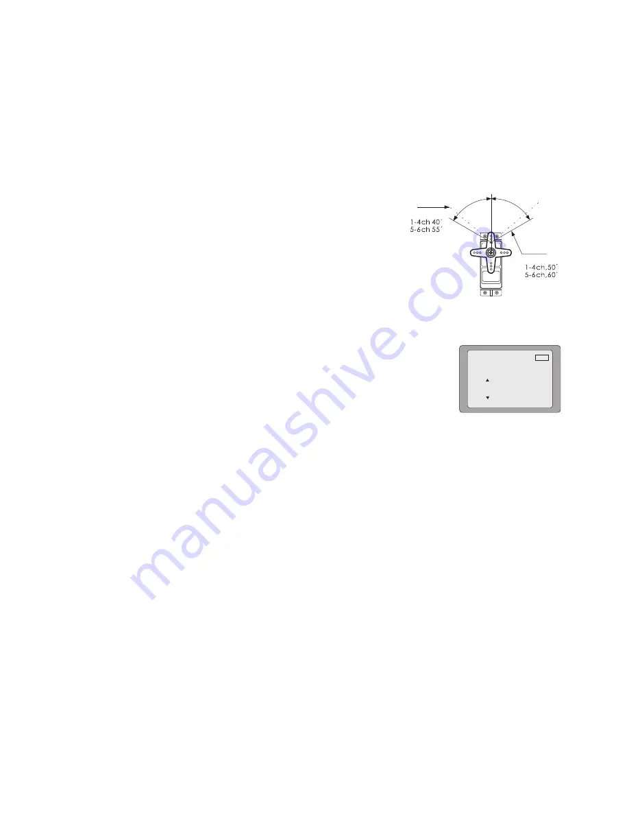
connections so the values can be set closer to 100%. (When the EPA is set to 
100% the maximum servo throw for channels 1, 2, 3 & 4 is approximately 40 

°


and approximately 55

°

 for channels 5 & 6.)

To set the end points:

1. Enter the programming mode and use the MODE key to access the “EPA” screen. The 
channel number being adjusted will show on the left side on the screen and the % symbol 
will be flashing. 
2. To change the RIGHT aileron throw move the aileron stick to the right, then push the 
DATA INPUT lever up or down to change the value and the throw. 

PPM

1

CH

100

%

Epa

3. Move the stick to the left and use the DATA INPUT lever to change the LEFT aileron throw. 
4. Use the SELECT key to display the other channels and set the other end points. Notice that moving the stick (or switch 
or dial) from one end to the other changes the value displayed and the position of the arrow for that “end” of the control 
input. 

TRIM - Trim Settings 

There are four trim levers (“trims”) on the front of the transmitter. Three of the trims are for adjusting the neutral position 
of the aileron, elevator and rudder servos. The fourth trim is for setting the idle r.p.m. of the engine when the throttle 
stick is all the way down. The intended use of the trims is to make small servo adjustments, in flight, to get the model 
properly “trimmed” (so it will fly straight-and-level). Because the trims are intended to be used while the model is in 
flight, you do not have to “enter the program” to adjust the trims. Simply push or pull on the trim levers while flying and 
the neutral position of the servos will shift. Keep in mind that you should start out with the control surfaces centered 
when the servos are centered and the trims are “zeroed” (or near zero). THEN you can adjust the trims once airborne. 

Center the servos: 

1. Turn on the transmitter and receiver. Operate the controls to make sure the servos respond in the correct direction. 
Use the reversing function to reverse any servos necessary. 

2. Center the throttle control stick. 

3. Place the servo arms on the servos so they are perpendicular to the pushrods (see page 5). It is okay to cut off any 
unused servo arms. 

4. Connect the pushrods to the control surfaces. Adjust the length of the pushrods until the control surfaces are 
centered when the servos are centered.

Note:  

The throttle trim affects the throttle servo only when the throttle stick is below “1/2 stick.” This way, the final closing of the 

carburetor can be adjusted without affecting the servo throughout the rest of the range.

9

Summary of Contents for T6EAP

Page 1: ...T6EAP T6EAP For Radiolink T6EAP 6 channel PPM FM modulation Radio control system for aircraft INSTRUCTION MANUAL Technical support available at http www radiolink com cn Radiolink Electronic ...

Page 2: ... system If this is your first computer radio rest assured that it is designed to make initial setup and field tuning of your airplane easier and more accurate than would be if using a non computer radio Although this is a beginner or sport system with the requirements of those flyers in mind in order to make the best use of your T6EAP and to operate it safely you must carefully read all of the ins...

Page 3: ...eron elevator and rudder Often different control throws are required for different types of flying Low throws may be required for flying at high speeds where the model s response becomes more sensitive and high throws may be required for aggressive aerobatic maneuvers or landing or flying at lower speeds where the model s response becomes less sensitive End point adjustment E P A Sets the overall ...

Page 4: ...rvo reversing and E P A on all channels dual rates exponentials and programmable mixing Additionally any one of four factory set preprogrammed wing type mixers including flaperon V tail elevon mixing may be selected Transmitter controls The diagram and explanations briefly describe the functions of the T6EAP transmitter Full instructions on how to operate the controls are provided beginning on pag...

Page 5: ...el has retractable landing gear this is the control used to extend and retract the gear Antenna Radiates signals to the receiver Never fly a model without fully extending the antenna or you may create interference to other modelers and decrease operational signal range of the transmitter The antenna may be removed and replaced with another in case it is inadvertently broken RADIO INSTALLATION Foll...

Page 6: ...cing the distance from the pilot that the model can be controlled range RECEIVER AND SERVO CONNECTIONS Connect the servos to the receiver to perform the functions indicated Receiver output channel Function 1 Aileron or right flaperon or right elevon for tailless models 2 Elevator or left ruddervator for V tail models or left elevon for tailless models 3 Throttle 4 Rudder or right ruddervator for V...

Page 7: ...ated at any time depending upon which model you choose to fly that day This eliminates the requirement for reconfiguring the transmitter each time you decide to fly a different model with it When the transmitter is turned on the model number model name modulation and the transmitter voltage will be indicated on the LCD screen Before every flight BE CERTAIN that the correct model number for the mod...

Page 8: ...inal factory defaults Often this function is done to get a fresh To reset data 1 Access the Model Select function in the programming mode by pressing the 2 MODE keys simultaneously and holding them down for one second Use the DATA INPUT lever to select the model memory you wish to reset 2 Once the desired model number is displayed on the screen press the SELECT key A REST will appear on the screen...

Page 9: ... response from that channel If the dual rates are inadvertently set to zero a crash could result Note When performing initial model setup the E P A s should be set prior to setting the dual rates When setting the E P A s for the first time on a new model the dual rates should be set to 100 PPM 1 CH 100 D R Dual Rate Settings To set the dual rates 1 Enter the programming mode Access the D R screen ...

Page 10: ...r up or down to change the value and the throw PPM 1 CH 100 Epa 3 Move the stick to the left and use the DATA INPUT lever to change the LEFT aileron throw 4 Use the SELECT key to display the other channels and set the other end points Notice that moving the stick or switch or dial from one end to the other changes the value displayed and the position of the arrow for that end of the control input ...

Page 11: ...xing function explained later where the channels to be mixed are factory set the T6EAP also contains one programmable mix for you the pilot determine the channels to be mixed This could be used to correct unwanted flight tendencies by mixing rudder to aileron or aileron to rudder for example PPM PMIX Inh To set up a programmable mix 1 Enter the programming mode Access the PMIX screen with the MODE...

Page 12: ...g you first need to cancel Elevon mixing However it is allowed to use Flaperon and V Tail mixing simultaneously 3 Push the DATA INPUT lever upward This will cause the flashing INH display to change to a flashing ON display Now the mixing is on 4 If needed to set ailerons differential Press the SELECT key to display the flashing sign Use the DATA INPUT lever to set the percentage of ailerons differ...

Page 13: ...PM V tl Inh PPM PPM PPM V tl V tl V tl On 50 2 Enter the programming mode Access the V TL screen with the MODE key You cannot set V tail mixing when Elevon mixing has already been set In order to enable V tail mixing you first need to cancel Elevon mixing However it is allowed to use V Tail and Flaperon mixing simultaneously 3 Push the DATA INPUT lever upward This will cause the flashing INH displ...

Page 14: ...ron or V TL mixing has already been set In order to enable Elevon mixing you first need to cancel both Flaperon and V tail mixing 3 Push the DATA INPUT lever upward This will cause the flashing INH display to change to a flashing ON display Now the mixing is on 4 Next you set the left wing to channel 1 aileron setting Press the SELECT key to display the CH1 and flashing sign Use the DATA INPUT lev...

Page 15: ...as Ch1 PPM Slv Ch4 PPM PMIX 0 PPM Flpr Inh PPM Flpr On PPM Flpr 0 PPM Fltr Inh PPM Fltr On PPM Fltr 0 PPM V tl Inh PPM V tl On PPM V tl 50 2 CH PPM V tl 50 4 CH PPM Elvn Inh PPM Elvn On PPM Elvn 50 1 CH PPM Elvn 50 2 CH To enter or leave Programming Mode press 2 MODE keys simultaneously for one second To change the Stick Mode turn on the transmitter holding both 2 MODE keys down simultaneously Use...

Page 16: ... in sync by toggling the trainer switch back and forth a few times The controls on the model should remain stationary If the controls do not remain stationary this indicates that the trim settings on the student s radio do not match those on the instructor s radio Adjust the student s trims as necessary Note When the instructor initially depresses the trainer switch on his transmitter there will b...

Page 17: ...e is necessary otherwise the receiver will not work 1 Place the transmitter and the receiver close to each other within one 1 meter 2 Turn on the transmitter 3 Check the LED that is placed on the back side of the transmitter to see if the RF signal is active When the green LED is ON solid the RF signal is being sent 4 Turn on the receiver 5 Press down the ID SET switch for more than one second and...

Page 18: ...T6EAP T6EAP For Radiolink T6EAP 6 channel PPM FM modulation Radio control system for aircraft INSTRUCTION MANUAL Technical support available at http www radiolink com cn Radiolink Electronic ...

Reviews: