D2112/D2112E Installation Manual
Page 8
74-07111-000-D 196
© 1995 Radionics
Keypads
Terminals 8, 9, and 10
You can connect up to four keypads to the panel.
The installation sheet packaged with each keypad
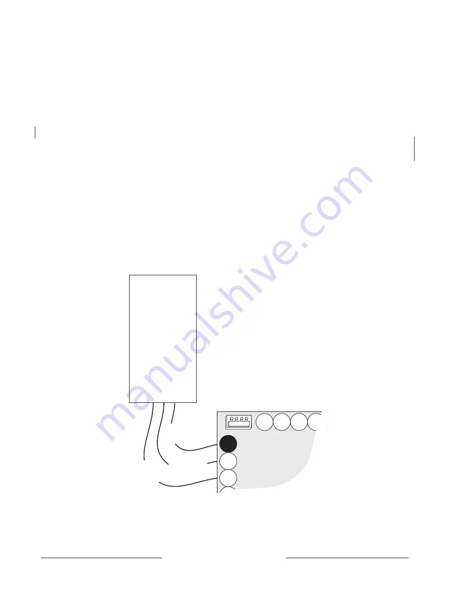
contains mounting instructions. Wire keypads to the
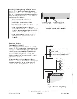
panel in parallel as shown in Figure 3.
You must use a minimum of five feet of wire (22
AWG) when connecting the keypad to the panel.
A short on terminal 9 within five feet of the panel
prevents the panel from operating correctly.
Maximum wire length for all keypads combined is
500 feet (22 AWG).
Extra power needed for more keypads: The D202
Keypad draws 45mA (125mA Alarm). Review
Power
Outputs on page 14 to determine the total power
output requirements for your system. Instructions for
using stand alone power supplies are included.
Auxiliary Power
Terminal 9
The continuous current draw for powered devices
connected to terminal 9, including keypads, must
not exceed 350mA (140mA for fire and combined
fire/burglary systems). Devices powered from this
output must operate over a range of 10.2 VDC to
13.9 VDC.
You must use a minimum of five feet (22 AWG) of
wire when connecting devices mounted outside
the enclosure to terminal 9. A short on terminal 9
within five feet of the panel prevents the panel from
operating correctly.
Checking Continuous Current Draw
The panel allows you to check current draw using
the keypad. For more information about this and
other keypad diagnostic features, see the
D2112
Keypad Diagnostics manual (74-07113-000).
Figure 3: Keypad Wiring
Keypad
Connect up to
four in parallel.
11
12
7
8
9
10
14
13
Red
(+12VDC)
Green
(Data)
Black
(Common)


