D2112/D2112E Installation Manual
Page 9
74-07111-000-D 1/96
© 1995 Radionics
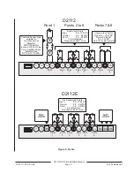
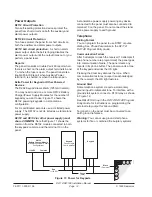
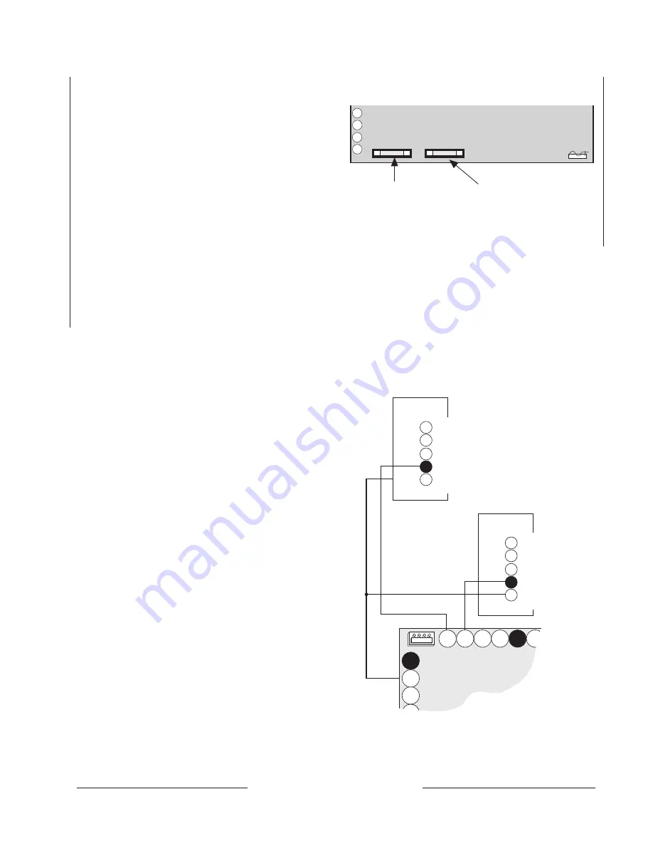
Figure 5: External Relay Wiring
1
2
Aux Power Fuse
2 Amp Fast Blow
Alarm Output Fuse
2 Amp Fast Blow
3
4
Figure 4: D2112E Fuse Locations
D133
Relay Module
N/O 1
COMM1
N/C 1
X1- ( Connect to terminal 12
for External Relay 2)
X1+
15
16
17
20
19
18
7
8
10
14
13
External Relay 1
External Relay 2
D133
Relay Module
N/O 1 (Closes to COMM1 when relay is activated.)
COMM1 (Common)
N/C 1 (Opens from COMM1 when relay is activated.)
X1- (Connect to terminal 11 for External Relay 1)
X1+ (Connect to terminal 9.)
9
11
12
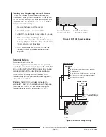
Testing and Replacing D2112E Fuses
The D2112E's Aux Power and Bell outputs are
protected by 2 Amp fast blow fuses. The fuses are
5 mm x 20 mm, 2 Amp Fast Blow (Radionics Part #
57-03570-008). To test the fuses, use a Volt/Ohm
meter to follow these steps:
1. Remove the fuse from the socket.
2. Switch the meter to measure Ohms.
3. Attach the meter leads to each side of the fuse.
4. If the meter does not change when you
connect the leads to the fuse, the fuse is open
(blown). Replace the blown fuse with a 5 mm x
20 mm, 2 Amp Fast Blow fuse.
5. If the meter measures 0 Ohms, the fuse is
closed (normal), and does not need to be
replaced.
External Relays
Terminals 11 and 12
You can program terminals 11 and 12 to provide
outputs for two external relays. Review the
RELAYS
Group in the D2112/D2112E Program Entry Guide
for a description of the relay functions available.
Connect a D133 Relay Module for each of the
external relay outputs you intend to use. Figure 5
shows the connections.
Warning: Install D133 modules connected to
terminals 11 and 12 in the enclosure with the panel
as shown in Figure 1. Do not connect wiring for
external devices directly to terminals 11 or 12.


