


D2412 Installation Manual
Page 11
© 1997 Radionics
8/11/97 P/N 35115B
RAM II ResetBye does not disarm the panel: After you
unlock the standby switch, the panel returns to a disarmed
state. Using RAM II
ResetBye, however, does not affect
the armed state of the panel.
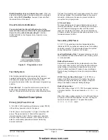
Check for Alarm Verification
You must check the Alarm Verification box in the
lower left hand corner of the Label if you programmed
Point 1 for Fire with Verification (Digit 1 = 2). See
POINT CODES in the Program Entry Guide for more
information.
Test the System
After finishing installation and programming, make a
complete functional test of the system. Test the panel and
all devices for proper operation. Test after you first
program the panel and after any subsequent programming
session.
Clear after test: To clear the alarm memory and report
buffer, close the Standby Switch for 2 seconds, then re-
lease it. The panel returns to service in the disarmed state.
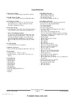
Detailed Description
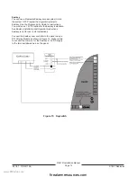
Primary (AC) Power Circuit
A 16.5 VAC, 40VA transformer (Radionics model D1640)
is the primary power source for the panel.
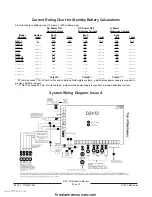
The AC power circuit provides 1.5 Amps of rectified DC
power. The panel reserves 140mA of this power for
internal operations and 1.0A for continuously powered
devices. Under alarm conditions 1.0A of power is avail-
able for continuously powered and alarm indicating
devices combined.
Transient suppressors and spark gaps protect the circuit
from power surges. This protection relies on the ground
connection. Make sure the panel’s ground terminal is
connected to a proper ground.
AC Power Failure
The panel indicates an AC power failure when power at
the terminals labeled 16.5VAC is missing for 60 seconds.
The
AC Fail Buzz/Rpt program item sets the panel’s
response to detected AC failure. The panel indicates an
AC power restoral 60 seconds after power restores to the
terminals labeled 16.5VAC.
Secondary (DC) Power
A 12V, 7.0 Ah sealed lead-acid rechargeable battery
(Radionics D126) supplies secondary power for auxiliary
and alarm outputs. The battery also powers the system
during interruptions in primary (AC) power.
Lead Acid Batteries Only: The panel charging circuit is
only calibrated for lead-acid batteries. Do not use gel-cell
or nicad batteries.
Battery Replacement
Radionics recommends battery replacement every three
to five years under normal use. Exceeding the maximum
output ratings, or installing the transformer in an outlet
that is routinely switched off, causes heavy discharges.
Routine heavy discharges can lead to premature battery
failure.
D135A Prevents Deep Discharge: The D135A Low
Battery Cutoff Module protects the battery from deep
discharge during extended power outages. Deep dis-
charge can cause permanent battery damage.
Battery Supervision
When the battery drops to 12.1 VDC the keypad indicates
a trouble condition. The panel transmits a
BATTERY LOW
report.
When the battery voltage returns to 13.0 VDC and there is
AC power at the terminals labeled 16.5VAC, the keypad
returns to normal operation. The panel transmits a
BATTERY RESTORAL
report.
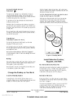
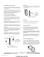
Figure 9: Programmer Jack
www.PDF-Zoo.com
firealarmresources.com


