D2412 Installation Manual
Page 13
© 1997 Radionics
8/11/97 P/N 35115B
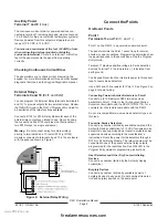
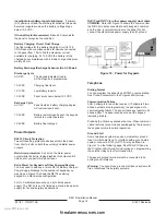
Figure 11: D133 for Ground Start
Points
Point Parameters
On-Board Point 1
Point 1 is a powered sensor loop. Review the Radionics
Technogram: Smoke Detectors Compatible with the
D2412 (P/N 35112) for a list of compatible detectors.
Point 1 is supervised with a 2K EOL resistor.
Points 2 to 6
Points 2 to 6 are supervised with 1.0K resistors.
Open Loop = Greater than 8.9 VDC, but less than
13.9 VDC.
Normal Loop = Greater than 2.5 VDC, but less than
8.5 VDC.
Shorted Loop = Greater than 0.0 VDC, but less
than 2.0 VDC.
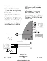
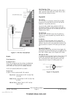
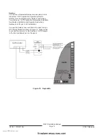
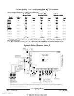
Figure 12: Keyswitch
Point Response Time
The panel scans point sensor loops every 500 millisec-
onds. A point must be faulted for 2 scans (one second)
before the panel initiates an alarm.
Keyswitch
Description
You can connect a momentary contact arming station
(keyswitch) to turn the D2412 on and off. Connect the
keyswitch to any point sensor loop.
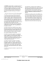
You can use the external relay outputs and D133 (or
D134) Relay Modules to activate arming status lights or
keyswitch arming stations. See the
Relays section in the
Program Entry Guide.
Programming
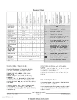
See the POINT CODES Group in the
Program Entry
Guide for the correct programming for points used for
keyswitches.
Installation
Connect the end-of-line resistor for the point at the
keyswitch so that the switch shorts the resistor when it
operates. An open on the circuit produces an alarm if the
area is armed and a trouble if it is disarmed. See Figure
12.
Keyswitch Operation
Shorting and restoring the point sensor loop toggles the
system ON and OFF. All faulted points are bypassed. See
the POINT CODES Group in the
Program Entry Guide.
Silencing the Bell
To silence the bell (stop Alarm Output) if the system in ON
(or part ON), operate the keyswitch to turn the system
OFF. If the area is OFF, operating the keyswitch only
silences the bell. It does not turn the system ON.
www.PDF-Zoo.com
firealarmresources.com


