


D2412 Installation Manual
Page 15
© 1997 Radionics
8/11/97 P/N 35115B
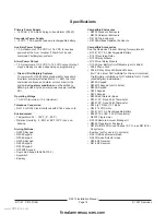
Installation Guide
for UL Applications
Introduction
The
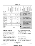
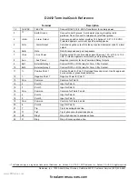
System Chart references components evaluated and
listed by Underwriters’ Laboratories for compatibility with
the panel. These components meet the basic system
requirements for the applicable standard.
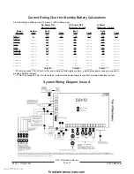
The
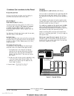
System Wiring Diagram, Issue A shows the relation-
ship between the panel and the accessory components
referred to in the
System Chart. See the installation and
operation instructions for each component for detailed
instructions.
Optional Compatible Equipment
You can use UL listed components that do not require
evaluation for electrical compatibility in many applications
when installed in accordance with the manufacturer’s
instructions.
Burglary Applications
You can use UL listed burglary alarm sensors that do not
require evaluation for electrical compatibility in burglary
applications. In some cases you must use a UL listed
Radionics interface module in conjunction with the
sensors. Consult the individual component specification
and installation documents to determine suitability.
In burglary applications with one 7.0 Ah, 12 VDC battery,
the panel supports an auxiliary output of 1.0A and an
alarm (bell) output of 1.85A configured as necessary. For
additional loadings refer to the
Current Rating Chart for
Standby Battery Calculations.
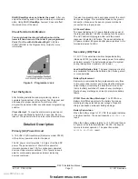
For commercial burglary installations, use a maximum of
45 seconds of entry delay and a maximum of 60 seconds
of exit delay.
Test Weekly: UL Standard 1023 requires a weekly test.
Configure the User System Test to test the battery. See
Configuration in the Program Entry Guide for instructions.
Fire Applications
You can use UL listed fire initiating devices not requiring
electrical compatibility evaluation in any application. For
example: four-wire smoke detectors, heat detectors,
waterflow switches, and manual pull stations are suitable
fire initiating devices. Consult the individual component
specification and installation documents to determine
suitability.
When using four-wire smoke detectors, install a suitable
power supervision unit according to the manufacturer’s
instructions. Use the D133 (or D134) Relay Module to
provide reset capability.
In fire applications with one 7.0Ah, 12 VDC battery, the
panel supports an auxiliary output of 140mA; it supports a
total combined continuous and alarm current draw during
alarm conditions of 1.0A. For additional loadings refer to
the
Current Rating Chart for Standby Battery Calculations.
Two-wire detectors must be electrically compatible, and
must be UL listed for use with the D2412. See the
Radionics
Technogram: Smoke Detectors Compatible
with the D2412 (P/N 35112), or you may contact the
detector manufacturer.
Test Weekly: Radionics recommends testing fire and
combined fire/burglary systems weekly. Configure the
User System Test to test the battery. See
Configuration in
the
Program Entry Guide for instructions.
For all Burglary applications, the panel must be pro-
grammed to send a supervisory signal to the central
station a minimum of once every 24 hours. Do not set or
program an automatic telephone dialer or similar device to
place a call to a police station number that is not specifi-
cally assigned by that station for such service.
Sounding Device
The sounding device shall operate for at least four minutes
before an automatic cutoff for Household Burglary
applications and at least 15 minutes for Commercial
Burglary applications.
For all Commercial Burglary applications, the system must
be programmed to sound the audible device every time
the system is armed.
Enclosures
The D2203 enclosure is suitable for Household Fire and
Burglary applications only.
Enclosure tamper protection causing an immediate alarm
signal is required for all burglary applications.
Radionics offers three optional enclosures:
The D8103 enclosure is suitable for residential fire and/or
burglary installations and commercial applications. See
System Chart for acceptable applications.
The D8109 is normally used for fire alarm applications.
The D8109 is approved by the Factory Mutual, California
State Fire Marshal, and the New York City Materials and
Equipment Acceptance System.
www.PDF-Zoo.com
firealarmresources.com


