

D2412 Installation Manual
Page 16
8/11/97 P/N 35115B
© 1997 Radionics
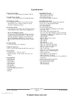
The D8108A is attack resistant. It is intended primarily for
UL commercial burglary and mercantile safe and vault
applications requiring a local bell. You can use the D8108A
in an burglary application where the D8103 or D8109
enclosure is suitable. The D8108A is approved by the
Factory Mutual, California State Fire Marshal, and the
New York City Materials and Equipment Acceptance
System.
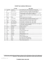
(
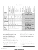
The System Chart can be found on the following page.)
The D2412 control panel is suitable for Police Station
connect applications, including Grade A Mercantile
Premises and Grade A Mercantile Safe and Vault alarm
systems. Suitable for Grade AA Mercantile Premises and
Grade AA Mercantile Safe and Vault alarm systems when
the Model D2412 DACT unit is installed in conjunction
with the Model D8122 derived channel subscriber terminal
unit. For all Police Station applications and grades, the
Model D8108A Attack Resistant Enclosure with a UL listed
local sounding device is required. Per UL 365,
keyswitches mounted outside the protected area must
employ high security locking cylinders complying with the
requirements for key locks, UL 437. Tamper protection
must also be provided.
The D2412 control panel is suitable for Local, Grade A
Mercantile Premises and Local, Grade A Mercantile Safe
and Vault alarm systems. For all Local applications and
grades, the D8108A Attack Resistant Enclosure and a UL
listed Local sounding device are required. Per UL 609,
when keyswitches are mounted outside the protected
area, tamper protection must be provided.
The D2412 control panel is suitable for Central Station,
Grade C applications. It is suitable for Central Station,
Grade B applications when the Model D2412 DACT unit is
installed with a UL listed Local sounding device. Also
suitable for Central Station Mercantile, Grade AA applica-
tions when installed with the Model D8122 derived
channel subscriber terminal unit.
The D2412 control panel is suitable for Proprietary
Burglar Alarm, Grade C applications. Also suitable for
Proprietary Burglar Alarm, Grade B applications when
Model D2412 DACT unit is installed with a UL listed Local
sounding device. Also suitable for Proprietary Burglar
Alarm, Grade AA when the Model D2412 DACT unit is
installed with a Model D8122 derived channel subscriber
terminal unit.
The D2412 control panel is suitable for Household, Grade
A applications.
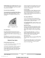
UL Standard 681 for Installation and Classification of
Mercantile and Bank Burglary Alarm systems requires foil
lining of equivalent protection of the control unit enclosure.
The D8108A enclosure does not have foil lining, but
acceptable protection can be provided by mounting
electronic vibration sensors inside the enclosure.
Proxim-
ity alarms (capacitance) cannot be used for this
purpose.
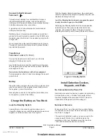
Install electronic vibration sensors in the D8108A enclo-
sure that are identical to those used to protect the safe or
the vault. Sentrol 5402, Potter EVD-S, or Arrowhead S-
3810 electronic vibration detection (EVD) systems which
can be mounted inside the enclosure meet the require-
ments of UL 681. Mount the electronic vibration sensor
directly inside the metal cabinet of the D8108A. Do NOT
install the sensor within a quarter inch (1/4”) of the
components or traces of the printed circuit assembly.
www.PDF-Zoo.com
firealarmresources.com


