background image

D2412 Installation Manual

Page 18

8/11/97   P/N 35115B

© 1997 Radionics

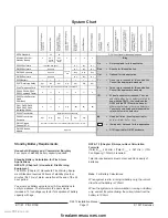
Current Rating Chart for Standby Battery Calculations

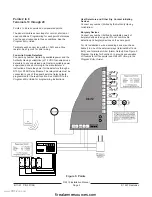
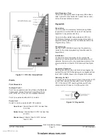
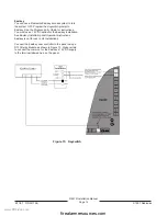
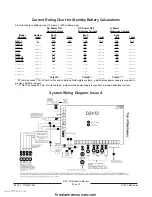
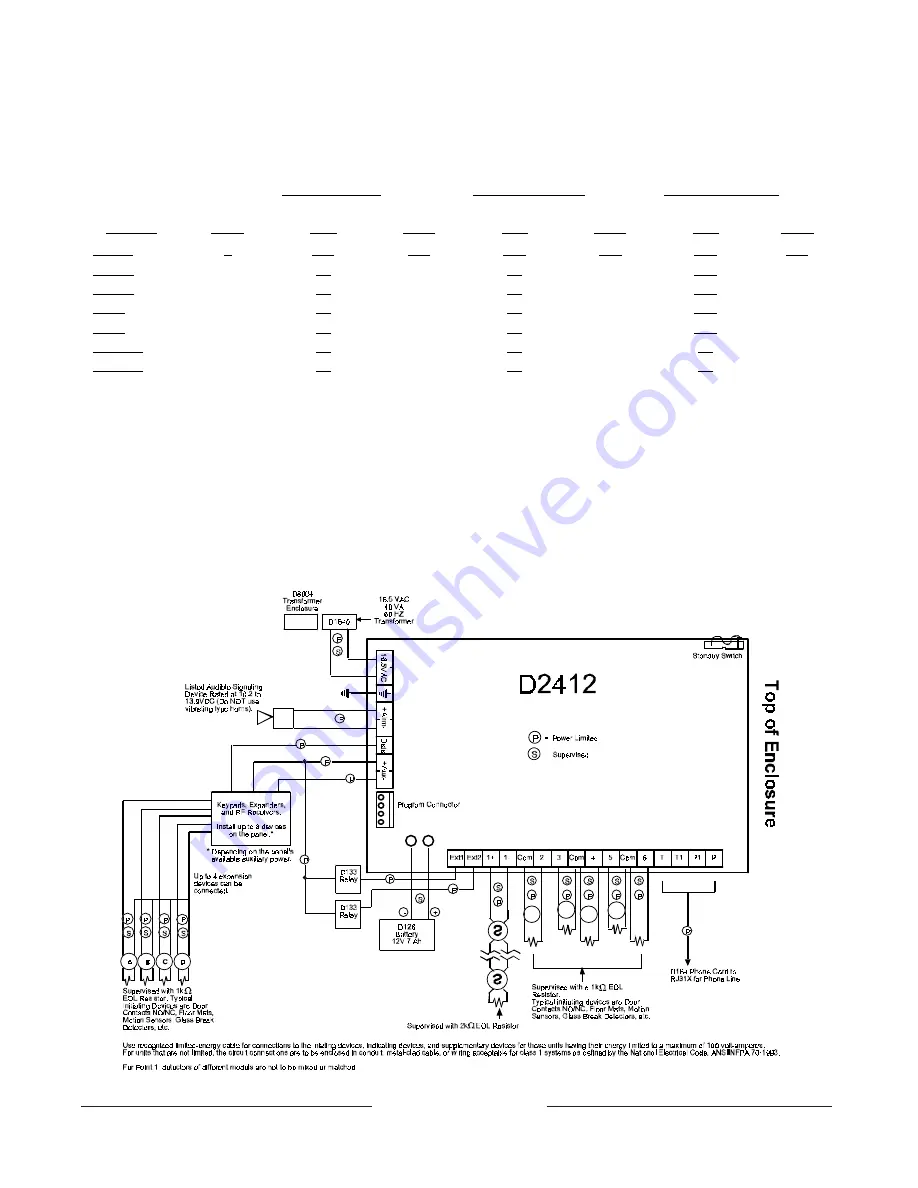
System Wiring Diagram, Issue A

All currents are in milliamperes (1 ampere = 1000 milliamperes)

AC Power ON
Normal Current

AC Power OFF
Minimum Current

In Alarm
Maximum Current

Model

Number

Number

Used

Each

Unit

Total

Each

Unit

Total

Each

Unit

Total

D2412

1

125

125

125

125

190

315

D202A

_____

45

_____

45

_____

125

_____

D220A

_____

30

_____

30

_____

125

_____

D222

_____

30

_____

30

_____

140

_____

D223

_____

30

_____

30

_____

140

_____

D208RF

_____

50

_____

50

_____

50

_____

D216RF

_____

50

_____

50

_____

50

_____

_______

_____

___

_____

___

_____

___

_____

_______

_____

___

_____

___

_____

___

_____

_______

_____

___

_____

___

_____

___

_____

_______

_____

___

_____

___

_____

___

_____

_____

Total A* =

_____

Total B =

_____

Total C** =

_____

*  If Total A exceeds 1.0A (140mA for fire and combined fire/burglary systems, a stand-alone power supply is required to
provide additional current.
**  If Total C exceeds 860 mA, for fire systems, a stand-alone power supply is required to provide additional current.

www.PDF-Zoo.com

firealarmresources.com

Summary of Contents for D2412

Page 1: ...8 11 97 P N 35115B 1997 Radionics D2412 Control Communicator Installation Manual www PDF Zoo com firealarmresources com ...

Page 2: ...so you will be advised of your right to file a complaint with the FCC if you believe it is necessary The telephone company may make changes in its facilities equipment operations or procedures that could affect the operation of the D2412 If this happens the telephone company will provide advance notice in order for you to make the necessary modifications to maintain uninterrupted service If you ex...

Page 3: ... Checking Continuous Current Draw 8 External Relays 8 Connect the Points 8 Point 1 8 Points 2 to 6 9 Point Wiring Diagram 9 Point Expanders Wired or RF 10 Make the Telephone Connections 10 Power Up 10 Program the Panel 10 Unlock the Standby Switch 10 Fill out the Delay Chart 11 Test the System 11 Detailed Description 11 Primary AC Power Circuit 11 Secondary DC Power 11 Power Outputs 12 Telephone 1...

Page 4: ...07032 000 D206 Keypad Each D206 includes the following D206 Keypad Installation Sheet 31946 Security System User s Guide 71 07117 000 Getting Started with Your Security System 71 07372 000 Three wire data cable assembly 15 07032 000 D220A Keypad Each D220A includes the following D220A Keypad Installation Sheet 74 07363 000 User s Reference Card 71 05432 011 Security System User s Guide 71 07374 00...

Page 5: ...istance before installing smoke detectors Short the end of line resistor before metering the wire Resistance on the sensor loops for Points 2 to 6 must be less than 100Ω with the end of line resistor shorted and the detection devices connected Maximum wire length for the transformer is 50 feet 18 AWG stranded Maximum wire length for all keypads and point expanders combined is 500 feet 22 AWG EMI E...

Page 6: ...lug the connector on the positive red battery wire to the positive side of the battery Charge the Battery as You Work Lock the Standby Switch Locking the pin in the standby position allows you to charge the battery as you install the detection devices and keypads Lock the pin down now See Figure 2 With the Standby Switch locked down the panel deacti vates the external relay outputs suppresses repo...

Page 7: ...n NSC This total must be less than 140mA 2 Subtract the NSC current required calculated in step 1 from the Primary Alarm Current 860mA The difference is the Alarm Current available for the Alarm Output terminals In formula format Primary Alarm Current NSC current required Alarm Current available Keypads Terminals 6 7 and 8 Data and Aux You can connect a combination of up to eight keypads and two t...

Page 8: ...t 1 on the D2412 is a powered supervised point The panel monitors the Point 1 sensor loop for normal shorted or open conditions Programming determines how the panel responds to those conditions See the Program Entry Guide Terminal 11 provides positive voltage to 2 wire detection devices Terminal 12 the loop return is isolated from earth ground The Keypad Reset function interrupts power to this sen...

Page 9: ...oute the power for the detectors through a D133 or D134 Relay Module The relay module must be connected to one of the panel s external relay outputs programmed for the reset function See RELAYS in the Program Entry Guide for programming instructions Heat Detectors and Other Dry Contact Initiating Devices Connect any number limited by the Authority Having Jurisdiction Burglary Devices Connect any n...

Page 10: ...After installation confirm that the panel seizes the line acquires dial tone reports correctly to the receiver and releases the phone line to the in house phone system Phone Cord Connect the flying leads of the D160 or D164 Phone Cord to the panel as shown in Figure 7 Connect the modular end to the RJ31X Power Up Connect the battery and then plug in the transformer Leave the Standby Switch locked ...

Page 11: ...e ground connection Make sure the panel s ground terminal is connected to a proper ground AC Power Failure The panel indicates an AC power failure when power at the terminals labeled 16 5VAC is missing for 60 seconds The AC Fail Buzz Rpt program item sets the panel s response to detected AC failure The panel indicates an AC power restoral 60 seconds after power restores to the terminals labeled 16...

Page 12: ...add one or more D8132 Battery Charger Power Supply Modules for the number of keypads you want to use Figure 10 shows the D8132 powering keypads in a stand alone configuration For UL Certificated accounts use a UL listed power supply The D8132 is not UL listed as a stand alone power supply for fire and burglary applications D2412 and D8132 or other power supply must share COMMON Note that Figure 10...

Page 13: ... and off Connect the keyswitch to any point sensor loop You can use the external relay outputs and D133 or D134 Relay Modules to activate arming status lights or keyswitch arming stations See the Relays section in the Program Entry Guide Programming See the POINT CODES Group in the Program Entry Guide for the correct programming for points used for keyswitches Installation Connect the end of line ...

Page 14: ...uctions You must use a 12 VDC option for the Easikey installation See Easikey Installation and Operation Instructions Easikey is not for use in UL installations Connect the Easikey door controller to the panel using a D133 Relay Module as shown in Figure 13 Make certain to connect the common for the Easikey s 12 VDC supply to the terminal labeled Aux on the panel Figure 13 Keyswitch www PDF Zoo co...

Page 15: ...etermine suitability When using four wire smoke detectors install a suitable power supervision unit according to the manufacturer s instructions Use the D133 or D134 Relay Module to provide reset capability In fire applications with one 7 0Ah 12 VDC battery the panel supports an auxiliary output of 140mA it supports a total combined continuous and alarm current draw during alarm conditions of 1 0A...

Page 16: ...otection must be provided The D2412 control panel is suitable for Central Station Grade C applications It is suitable for Central Station Grade B applications when the Model D2412 DACT unit is installed with a UL listed Local sounding device Also suitable for Central Station Mercantile Grade AA applica tions when installed with the Model D8122 derived channel subscriber terminal unit The D2412 con...

Page 17: ...ndby plus four minutes 067 hrs of alarm operation at the end of the 24 hour period You must use battery ampere hour Ah calculations to verify compliance The formula in the next column includes a 10 contingency factor for depletion of battery capacity with age NFPA 72 Chapter 2 Ampere Hour Calculation Formula Total B ___ x 24 Hrs Total C ___ x 067 Hrs 10 Contingency Total Ah required Total Ah requi...

Page 18: ..._ D222 _____ 30 _____ 30 _____ 140 _____ D223 _____ 30 _____ 30 _____ 140 _____ D208RF _____ 50 _____ 50 _____ 50 _____ D216RF _____ 50 _____ 50 _____ 50 _____ _______ _____ ___ _____ ___ _____ ___ _____ _______ _____ ___ _____ ___ _____ ___ _____ _______ _____ ___ _____ ___ _____ ___ _____ _______ _____ ___ _____ ___ _____ ___ _____ _____ Total A _____ Total B _____ Total C _____ If Total A excee...

Page 19: ... Keypad D205 Keypad D206 Keypad D220A Keypad D222 Keypad D223 Keypad D204RF Keypad Keychain Keypad 60 606 319 5 Keyswitch Easikey Compatible Enclosures D2203 Standard Enclosure D8103 Universal Enclosure D8109 Fire Enclosure D8108A Attack Resistant Enclosure Compatible Accessories See the Radionics Product Catalog for complete list D126 12V 7 Ah Rechargeable Battery D127 Reversing Relay D133 Relay ...

Page 20: ...ive output for continuously powered devices 1 0A at 10 2 to 13 9 VDC Protected against overcurrent by self resetting device 8 Aux Aux Power Negative common for Aux Power and Relay Outputs 9 Ext1 External Relay 1 Connect D133 or D134 relay for Form C Dry Contact 10 Ext2 External Relay 2 Connect D133 or D134 relay for Form C Dry Contact 11 1 Positive Point 1 Positive Power for Point 1 Switched for s...

Reviews: