D2412 Installation Manual
Page 3
© 1997 Radionics
8/11/97 P/N 35115B
Table Of Contents
Introduction .................................................... 4
D2412 Control / Communicator ........................ 4
Ordered Separately .......................................... 4
Enclosure Options ............................................ 4
Listings and Approvals ..................................... 5
Getting Started .............................................. 5
Mount the Enclosure ......................................... 5
Run the Premises Wiring .................................. 5
Connect to Earth Ground .................................. 6
Transformer ...................................................... 6
Battery ............................................................... 6
Charge the Battery as You Work .................. 6
Lock the Standby Switch ................................... 6
Install Detection Devices, Keypads, Bells.... 6
No Connection to the Panel Yet ........................ 6
Number of Sensors ........................................... 6
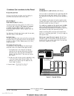
Continue Connections to the Panel ............. 7
Power Down First ............................................. 7
Alarm Output ..................................................... 7
Keypads ............................................................ 7
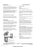
Auxiliary Power ................................................. 8
Checking Continuous Current Draw ................. 8
External Relays ................................................. 8
Connect the Points ........................................ 8
Point 1 ............................................................... 8
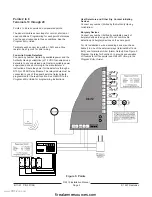
Points 2 to 6 ...................................................... 9
Point Wiring Diagram ....................................... 9
Point Expanders, Wired or RF .......................... 10
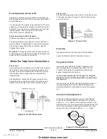
Make the Telephone Connections ................ 10
Power Up .......................................................... 10
Program the Panel ............................................ 10
Unlock the Standby Switch ............................... 10
Fill out the Delay Chart ..................................... 11
Test the System ................................................. 11
Detailed Description ...................................... 11
Primary (AC) Power Circuit .............................. 11
Secondary (DC) Power ..................................... 11
Power Outputs .................................................. 12
Telephone ......................................................... 12
Points ................................................................ 13
Keyswitch .......................................................... 13
Easikey Diagram ............................................... 14
Installation Guide for UL Applications ......... 15
Introduction ....................................................... 15
Optional Compatible Equipment ...................... 15
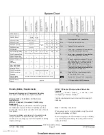
System Chart ................................................. 17
Standby Battery Requirements ......................... 17
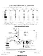
System Wiring Diagram, Issue A.................. 18
Specifications ................................................ 19
D2412 Terminal Quick Reference ................. 20
www.PDF-Zoo.com
firealarmresources.com


