D2412 Installation Manual
Page 9
© 1997 Radionics
8/11/97 P/N 35115B
Points 2 to 6
Terminals 13 through 20
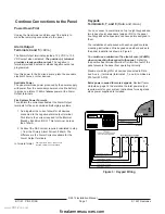
Points 2 to 6 are supervised, non-powered points.
The panel monitors sensor loops for normal, shorted, or
open conditions. Programming for each point determines
how the panel responds to those conditions. See the
Program Entry Guide.
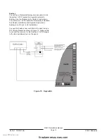
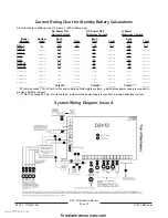
Terminate each sensor loop with a 1.0k
Ω
end-of-line
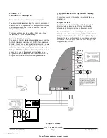
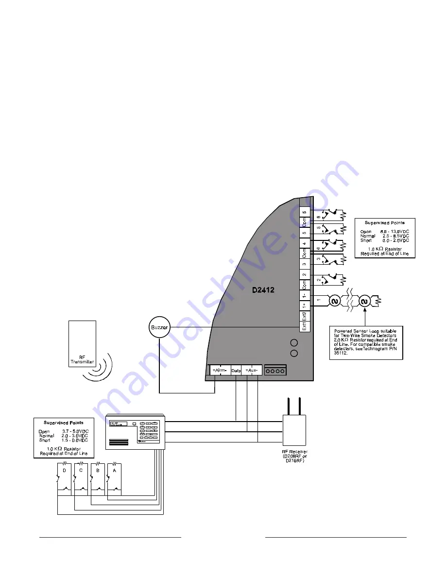
resistor. See Figure 5 for point wiring.
Four-wire Smoke Detectors
Connect any number (limited by available power and the
Authority Having Jurisdiction) of 12 VDC four-wire smoke
detectors to any supervised point. Install a suitable power
supervision device according to the manufacturer’s
instructions. Route the power for the detectors through a
D133 (or D134) Relay Module. The relay module must be
connected to one of the panel’s external relay outputs
programmed for the reset function. See
RELAYS in the
Program Entry Guide for programming instructions.
Heat Detectors and Other Dry Contact Initiating
Devices
Connect any number (limited by the Authority Having
Jurisdiction).
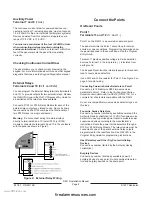
Burglary Devices
Connect any number (limited by available power) of
burglary devices to any point. Do not combine fire
detection and burglary devices on the same point.
For UL installations, wire a sounding device (such as a
buzzer) to one of the external relays (terminals Ext1 and
Ext2) and to teAlrm (Alarm Output). See Figure 5.
Program the relay for Function 3 to provide annunciation
of troubles for all fire points (see
RELAYS Group in the
Program Entry Guide).
Figure 5: Points
www.PDF-Zoo.com
firealarmresources.com


