background image

D6680

Network Adapter

Installation Guide

1.0

Introduction

The Radionics D6680 Network Adapter is a two-channel network adapter. The D6680 includes a cable for
connecting to DB25 Channel 1 Port. For most NetCom installations, only one channel needs to be used and
configured.


These instructions should be followed to avoid the possibility of physical damage to the operator,
program and/or equipment.

1.1

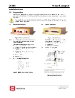
Network Interface

Figure 1: Network Interface

Note:

Do not attempt to connect both Ethernet ports
simultaneously. The D6680 does not have
routing capabilities.

The D6680 has the following items on the
Network Interface end of the unit.
1.  10BASE-T Ethernet Port (refer to Figure 2)

2.  10BASE-FL Ethernet Port (Transmit)

– Not Used

3.  10BASE-FL Ethernet Port (Receive)

– Not Used

4. Network 

LEDs

5. Power 

Plug

1.1.1

RJ-45 10BASE-T Ethernet Port

Figure 2: RJ-45 Ethernet Jack Pinouts

1.2

Serial Interface

Figure 3: Serial Interface

The D6680 has the following items on the
Serial Interface end of the unit.
1.  DB9 Serial Port (DTE) – Not Used

2. Serial 

LEDs

3.  DB25 Serial Port (DCE)

1.2.1

DB25 Serial Port (DCE)

Figure 4: 25-pin Serial Port

Summary of Contents for D6680

Page 1: ... not attempt to connect both Ethernet ports simultaneously The D6680 does not have routing capabilities The D6680 has the following items on the Network Interface end of the unit 1 10BASE T Ethernet Port refer to Figure 2 2 10BASE FL Ethernet Port Transmit Not Used 3 10BASE FL Ethernet Port Receive Not Used 4 Network LEDs 5 Power Plug 1 1 1 RJ 45 10BASE T Ethernet Port Figure 2 RJ 45 Ethernet Jack...

Page 2: ...port Diagnostic LEDs Network Transmit Network Receive Good Link Collisions Channel 1 Status Channel 2 Status Diagnostic Compatibility Ethernet Version 2 0 IEEE 802 3 D6600 Power Requirements 9 to 30 VDC or 9 to 25 VAC External adapter included Power Consumption 3 W AC Current Required UPS Standby Current 35 mA Power Input AC nominal operating range 120 or 240 VAC AC maximum operating range 100 to ...

Page 3: ...nstalling the D6680 in the AE1 or AE2 enclosure the correct mounting holes must be found on the back wall of the enclosure Only these holes line up correctly to allow the D6680 to be secured with two screws Once the holes are found proceed to mount the D6680 1 Place the D6680 against the back wall of the enclosure 2 Line up the side mounting holes on the D6680 with the enclosure mounting holes ind...

Page 4: ... cover plate using the 6 machine screws nuts and lockwashers provided Mount the cover plate to the gang box with the 10 screws provided with the gang box 6 Energize the power to the circuit s and using a voltmeter test the duplex outlet for proper voltage 7 Punch out a conduit knockout in the low voltage side of the gang box Bring the low voltage wiring through the knockout hole and into the gang ...

Reviews: