background image

D7212 Installation and Troubleshooting Quick Reference

Page  5

74-06914-000-A 8/93

© 1993 Radionics

NCI #215

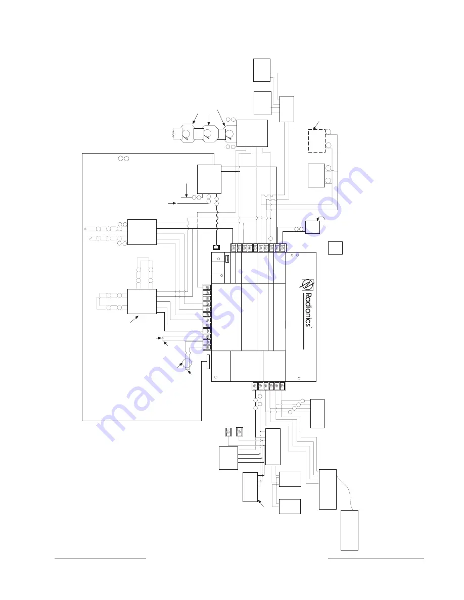
System Wiring Diagram, Issue A

Digital Alarm 

Communicator 

T

ransmitter

P

P

P

P

P

S

D122 DUAL


BA
TTER

Y

 HARNESS

Low Battery

LEDs Off When Normal

LINE SNIFFER SELECT

Loop Start

Ground Start

TELCO 

CORD

MODEL

 No. 

D161

PHONE 

 LED

ON  WHEN 

COMMUNICA

TING

OFF  WHEN IDLE

EXP

PORT

Operation Monitor 

Pulses When Normal

Flickers When Ringing

Solid When Held In Reset

PROG

CONN

RED

GROUND

ST
ART 

Requires

Relay

#D136

In J5

YEL

RED

D7212

Reset Pin

Disable 

All Except Battery 

Charging 

And Local Programming

GRN

Charging Status 

Reference Manual #74-06144-000 figure #19 For W

iring Diagram

Reference Document  #73-06143-000 for Compatible Smoke Detectors

ARMING ST

A

TION

T

O

 RJ31X FOR

PRIMAR

Y


PHONE LINE

T

O

 RJ31X FOR

SECONDAR

Y


PHONE LINE

16 V

A

C

40 V

A

60 HZ

TRANSFORMER

AS 

REQUIRED

D1255/D720

UP
 T

O

 EIGHT

SUPER

VISED

D105 FL

 EOL


DEVICE 

GND 

AUX

OUT 

IN

D128

D105  FL

EOL

 DEVICE

(FOR TYPICAL

 BURGLAR 

ALARM APPLICA

TIONS)

SUIT

ABLE FOR V

A

L

VE 

T

AMPER 

AND OTHER 

TYPES OF 

EXTINGUISHING SYSTEM 

SUPER

VISION.

TYPICAL

 INITIA

TING DEVICES 

ARE 

DOOR CONT

ACTS NO/NC, FLOOR 

MA

TS, MOTION SENSORS, GLASS 

BREAK DETECT

ORS, ETC.

UP
 T
O

 40 

D8127 U/T


POPITS

DATA

AUX

GND

D8125 POPEX

28

27

32

31

30

29

8

7

6

5

4

3

1

11
12

13
14
15
16
17

18
19
20

21

22

2

9

10

P

P

S

S

- +

- +

D125

1 10 3 4 2

         o

r

         5

L

O

O

P


A

D129

6 7 5 8 9

1

2

3

4

10 1

1

 12 13 

D129 PROVIDES OPTIONAL


W

A

TERFLOW ALARM 

RET

ARD 

FEA

TURE. NOT

 SUIT

ABLE FOR 

2-WIRE SMOKE DETECT

ORS. 

NOTE: USE ZERO RET

ARD EXCEPT


FOR W

A

TERFLOW

.

LOOP

 B

D192A

P

P

S

S

+

-

ECL

 DEVICE 15-03130-001

LISTED  

AUDIBLE 

SIGNALING 

DEVICES 

RA
TED A

T

 10.2 

T

O

 13.8 VDC  

(DO NOT

 USE 

VIBRA

TING 

TYPE HORNS)

AUX      PWR

ALARM TRIG

              C

O

M

SUPV       IN

ALARM CKT

P

-

-

+

+

D126

BA
TTER

Y

12V 7Ah

D126

BA
TTER

Y

12V 7Ah

CONNECT

 UP


T

O

 SIX 

OCT

ORELA

YS

P

S

P

S

-

+

J3

P

S

P

S

P

S

P

S

= POWER LIMITED

= SUPER

VISED

D1640

17-05823-000

D8132

BA
TTER

Y

CHARGER

D126

BA
TTER

Y

12V 7Ah

D126

BA
TTER

Y

12V 7Ah

D8004 

TRANSFORMER 

ENCLOSURE

REQUIRED FOR FIRE 

INST

ALLA

TIONS.

P

ARALLEL


PRINTER

D9131 P

ARALLEL


PRINTER 

INTERF

ACE

AUX POWER 

T

O

 TERMINAL

 3

GND T

O

 TERMINAL

 9

4

3

31

ZX

D8128A

 OCT

OPOPITS 

UP
 T

O

 FIVE MAIXIMUM

Summary of Contents for D7212

Page 1: ...rminal Description 12 Introduction This reference contains the very basic information a trained installer needs to install and troubleshoot a D7212 system See the D7212 Operation and Installation Manu...

Page 2: ...are AREA IS ON AREA IS OFF Follow the procedure below to toggle between custom and default idle text 1 Ensure the command center is at idle text 2 Press COMMAND 5 7 3 The display will change to defau...

Page 3: ...connected to same ZONEX as a D8125 Connect only one OctoPOPIT with switch 12 ON to ZONEX If ZONEX is connected to a D8125 turn switch 12 OFF for all OctoPOPITs connected to that terminal POPIT is not...

Page 4: ...Faulted points do not generate alarms or troubles as programmed Command 47 pressed at the time the alarm or trouble was generated The D7212 ignores input from all points in the same area programmed fo...

Page 5: ...FOR TYPICAL BURGLAR ALARM APPLICATIONS SUITABLE FOR VALVE TAMPER AND OTHER TYPES OF EXTINGUISHING SYSTEM SUPERVISION TYPICAL INITIATING DEVICES ARE DOOR CONTACTS NO NC FLOOR MATS MOTION SENSORS GLASS...

Page 6: ...keys is stuck under the faceplate Press each of the keys on the command center to be certain none of them is stuck Data connections yellow and green wires on one or more command centers are reversed...

Page 7: ...is plugged securely into the D5200 programmer 3 Check each conductor in the data power cord for continuity AC induction through the on board point sensor loops the DATA BUS or the ZONEX BUS 1 Verify...

Page 8: ...s 1 and 8 5 Verify that all telephones are on hook Leaving a telephone on hold after the other party hangs up creates an off hook condition Verify that no phones are on hold If completing the steps ab...

Page 9: ...y signal for all ten attempts to reach the receiver Calls are not reaching the receiver 1 Verify that correct prefixes and phone numbers for the receiver have been programmed into the D7212 2 Verify t...

Page 10: ...7 8 SWITCHED AUX POWER Supplies up to 1 4 Amps at 10 0 VDC to 13 9 VDC Use terminal 9 for common Programmed as Relay C Continuous output interrupted by CMD 47 or alarm verification Shares circuit bre...

Reviews: